Services on Demand
Article
Latin American applied research
Print version ISSN 0327-0793
Lat. Am. appl. res. vol.32 no.3 Bahía Blanca July/Sept. 2002
Numerical model of steel slab reheating in pusher furnaces
P. Marino†, A. Pignotti‡ and D. Solís§
Centro de Investigación Industrial, FUDETEC, 2804 Campana, Argentina
† sidmrp@siderca.com
‡ api@siderca.com
§ sidpsol@siderca.com
Abstract — The difficulty in measuring load temperatures inside reheating gas furnaces may be circumvented by appropriate use of on-line numerical models. In this article we describe a model of pusher furnaces, used to reheat steel slabs. The model uses thermocouple measurements at fixed positions inside the furnace to calculate the temperature of the combustion products, and takes into account radiative exchanges among those gases, the furnace refractories and the load. A good correlation is found between a temperature profile measured after the slab leaves the roughing stands and the results of the numerical calculations. We conclude that the model is a powerful tool to monitor the thermal state of the load inside the furnace and is suitable, together with an appropriate control algorithm, to automatically calculate the furnace settings required ensuring the objectives of the heating process.
Keywords — Numerical modeling, Reheating furnaces, Steel industry, Zone method
I. INTRODUCTION
Gas-fired reheating furnaces are present in different manufacturing stages in the steel industry, such as rolling and heat treating of steel products. Monitoring the load temperature during these processes would be highly desirable in order to achieve the specified process standards, but is often either impossible or costly and cumbersome. Indeed, most measurements on the products are carried out once they are already outside the furnace.
Furnace operation is therefore based on production tables tailored to the range of manufactured products. These tables correspond, however, to steady-state operation, which is seldom achieved in continuous production lines because of various reasons: changes in product geometry, eventual changes in the inlet load temperature, and upstream or downstream events that may slow down and even temporarily halt the production schedule.
This article describes a numerical model that was developed as an aid to furnace operation, to overcome the difficulties of measuring load temperatures inside the furnace and in the interior of heated parts. The two leading applications are the improvement of set-up parameters in steady-state operation to increase productivity and the on-line control of the furnace operation to anticipate and avoid departures from established quality objectives during transients.
II. INDUSTRIAL APPLICATION
At our Center for Industrial Research, numerical modeling of reheating furnaces has been applied to four different kinds of furnaces (Altschuler et al., 2000): pusher type furnaces used for reheating slabs before rolling, rotary hearth furnaces for heating billets before piercing (Marino and Pignotti, 1997), walking-beam furnaces for heating steel tubes (Marino, 2000), and tunnel furnaces for continuous annealing of steel plate (Altschuler et al., 1999). In the following, we focus on the first of these applications, including model validation and comparison with some plant results.
A. Pusher Furnace
At the hot rolling facility of SIDERAR at San Nicolás, steel slabs are reheated up to 1200°C to be milled in the steel sheet production process. Reheating takes place in four 25m long gas-fired furnaces. Slabs 6m long, width between .8 and 1.4m, and thickness of .18 or .20m are oriented in a direction that is transverse to the furnace axis and proceed sideways, until they reach the furnace exit. At the other end, a slab is positioned in front of the furnace entrance, and is pushed in by a mechanical device when the furnace is ready to discharge a slab, thus generating a rigid displacement of the load inside the furnace.
For approximately two-thirds of the furnace length (heating zone) the slabs are supported by four refrigerated rails ("skids"), whereas in the last section (soaking zone) they lie on the hearth. In the upper and lower heating zones, there are burners that are responsible for most of the heating of the slabs. The presence of the skids, however, interferes with the heating of the slabs in their immediate vicinity, and generates temperature deviations commonly called"skid marks".
The time that the slab front end takes to arrive to the different rolling stages is shorter than that corresponding to the slab back end. Thus, the furnace zones that are responsible for the slab back section heating are set 20°C above those of the opposite side. This practice is called "differential heating".
B. Heating objectives
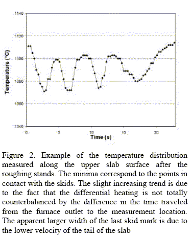
The objectives of the heating process are given in terms of the temperature distribution measured by an infrared pyrometer on the upper side of the slab after the roughing stands. Figure 2 shows an example of such a distribution. Lower measured temperatures at the skid positions are apparent. They should range between 1060 and 1100°C to obtain the steel temperature required at the end of the rolling process for the subsequent on-line heat treatment. Large slab temperature inhomogeneities should also be avoided because they may give rise to thickness variations beyond the values that can be corrected by adjusting the set-up of the last milling stage.
Figure 1. Longitudinal section of SIDERAR #3 pusher furnace
III. NUMERICAL MODELING
A. Model Main Assumptions
Because on-line modeling of the combustion and fluiddynamic processes inside a furnace is beyond our present computational capabilities, we focus on the radiative heat exchanges among walls, load and combustion gases. The temperature of the combustion products is calculated from the values measured by thermocouples inside the furnace that are used either to control or monitor it.
B. Radiative Exchanges
The zone method (Hottel and Sarofim, 1967) is used to calculate the radiative heat exchanges among gas, load and refractory elements. Due to the important dependence of the combustion products radiative properties on the wavelength, a spectral treatment of the radiative exchanges is used. The combustion gas properties as a function of the wavelength for a gas composition of 18% water vapor and 8% carbon dioxide are taken from RADCAL (Grosshandler, 1993). The dependence of the steel and refractory emissivity on the wavelength is taken from the measurements of Bauer and Steinhardt (1990).
Each one of the furnace chambers is treated as an independent cavity. For each one of them the load and refractory surfaces are divided into rectangular elements associated to the nodes used to solve the heat diffusion equation. The interior of each chamber is divided into N isothermal volumes. The temperatures of these gas volumes are obtained assuming that the N thermocouples that are used either to control or to monitor that furnace chamber are in a state of radiative equilibrium. Thus, a set of N nonlinear equations is solved for the combustion product temperatures by the Newton-Raphson method. With these and the wall and load temperatures, all the heat fluxes are calculated. Thus, the following system of equations is solved for every wavelength interval:

where:
Ak : area of surface element k
elk : spectral emissivity of surface k
dkj is 1 if k=j and 0 otherwise
Pl(T) : spectral emissive power of a blackbody at temperature T
qlj : net spectral heat flux at surface j
![]() and
and ![]() are the direct exchange factors calculated using the results given by Tucker (Rhine and Tucker, 1991)
are the direct exchange factors calculated using the results given by Tucker (Rhine and Tucker, 1991)
NS, NV are, respectively, the number of surface and volume elements.
The heat fluxes on the refractories and steel are obtained integrating the spectral heat fluxes from the above calculation. Subsequently, they are modified to take into account the shadow and contact effects at the skid locations. A simplified model of the radiative exchanges is used to calculate the heat fluxes on the slab vertical front and back ends.
Due to the fact that the spectral heat flux coefficients in the above equation are assumed to be independent of the combustion gas temperatures, they can be calculated in advance and stored in computer memory. This decreases the time required to simulate each time step and enables real time functionality.
Because of the limited number of thermocouples that are present in the combustion chambers, a rough discretization is used for the gas volumes. It is therefore advisable to verify experimentally the validity of this procedure.
C. Heat Conduction
The heat fluxes described above are the boundary conditions used to solve the heat diffusion equation in the slab. A two-dimensional description of the temperatures in the slabs is obtained neglecting temperature gradients in the slab width. The dependence of the steel properties on the temperature is taken into account using the data of the BISRA (1953).
A one-dimensional description of the heat conduction on the refractories is used to calculate the temperature distribution inside the furnace hearth and walls.
IV. MODEL RESULTS
A. Temperature Evolution
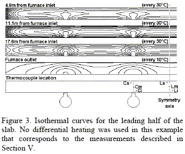
Figure 3 shows the isothermal curves calculated by the model for a case with no differential heating. Because of the front and back lateral heating, temperatures at the slab ends are higher during the initial heating stages. The slab temperature is minimal at the points in contact with the skids throughout the heating process.
B. Outlet temperatures
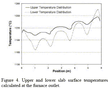
Figure 4 shows an example of the outlet longitudinal temperature distributions obtained with the model on the upper and lower slab surfaces when differential heating is present. The skid marks are visible from above, and downstream measurements show that they are enhanced during the rolling process.
V. MODEL VALIDATION
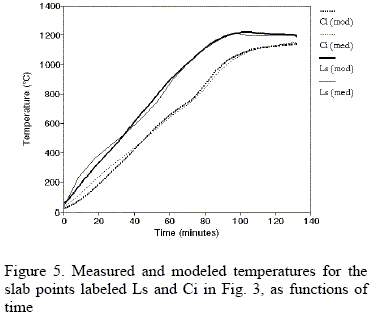
Model results were compared with thermocouple measurements made at SIDERAR in collaboration with TECHINT/ITALIMPIANTI. In those measurements, a slab was instrumented with six thermocouples that were placed at different slab positions, as shown in Figure 3, and were connected to a recording device that traveled inside a thermally insulating box fastened to the slab.
Even though the comparison shown in Figure 5 is quite good, some deviations are observed. They can be accounted for by the coarse discretization used for modeling the combustion gas volumes, due to the small number of thermocouples present inside the furnace.
VI. PLANT RESULTS
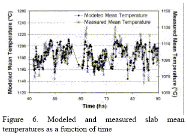
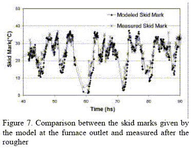
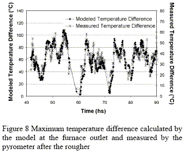
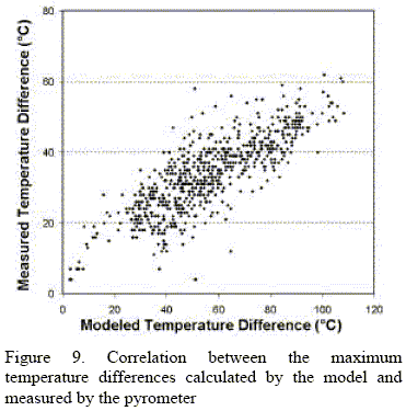
The model was installed on-line and used to calculate the temperature distribution of the slabs at the furnace outlet. In order to evaluate the usefulness of the calculated temperatures they were compared with the pyrometer measurements of the corresponding slab. To make a meaningful comparison, we refer to Fig. 2, in which an example of pyrometer readings is shown. From these measurements, we only take into account the values between the first and last minima in order to eliminate the points near the slab front and back ends, that cannot be modeled accurately because of lack of information on the exact location of such ends. Three parameters characterize this temperature distribution: the average slab temperature, the maximum temperature difference, and the "skid mark", defined as the maximum temperature difference after subtraction of the linear trend generated by the differential heating. These three parameters are obtained both for the pyrometer readings and the temperature distribution calculated by the model. Figures 6 to 9 show the comparison corresponding to a period of fifty hours. A good match is observed for the time dependence, but we point out that the temperature scales of the measured and modeled values are different. This is understandable because the slab thermal evolution between the furnace outlet and the pyrometer location, which includes the scale breaker and the rougher, is not modeled.
V. CONCLUSIONS
Although the model presented in this article involves several simplifying assumptions to allow real time simulation, very good correlations are obtained between the model results and the measured quantities that are used to monitor the slab heating quality. These results show that there is a great potential for controlling the process through the implementation of suitable control algorithms.
ACKNOWLEDGMENTS
The authors wish to acknowledge the support and technical assistance provided by R. Castilla, D. Biurrun, E. Ubici, A. Vigliocco and R. Musante of SIDERAR.
REFERENCES
1. Altschuler, E., Marino, P., Pignotti, A., Migliorino, D. and A. Jacobsen, "Numerical Model of #1 CGL Furnace at Siderar", Proceedings of the 91st Galvanizer's Conference, Jackson, Mississippi, October 24-27, 1999
2. Altschuler, E., Marino, P. and A. Pignotti, "Numerical Models of Reheating Gas Furnaces in the Steel Industry", Proceedings of the Fourth ISHMT/ASME Heat and Mass Transfer Conference, Pune, India, January 5-7, 2000
3. Bauer, W. and R. Steinhardt, "Measurements of Radiative Properties of Refractories and Steel", Eurotherm Seminar n° 17, Portugal 1990
4. BISRA (The British Iron and Steel Research Association), "Physical Constants of Some Commercial Steels at Elevated Temperatures", Butterworths Scientific Publications, London, 1953
5. Grosshandler, W., "RADCAL: A Narrow Band Model for Radiation Calculations in a Combustion Environment", NIST Technical Note 1402, 1993
6. Hottel, H. and A. Sarofim, Radiative Transfer, Mc Graw-Hill, New York (1967).
7. Marino, P. and A. Pignotti, "On-Line Model for Controlling an Industrial Rotary Reheating Gas Furnace", Proceedings of The Fourth European Conference on Industrial Furnaces and Boilers, Porto, Portugal, 1-4 April 1997
8. Marino, P., "Numerical Modeling of Steel Tube Reheating in Walking Beam Furnaces", Proceedings of The Fifth European Conference on Industrial Furnaces and Boilers, Porto, Portugal, 11-14 April 2000
9. Rhine, J.N. and R.J. Tucker, Modelling of Gas-Fired Furnaces and Boilers, British Gas, London (1991).
Received: June 15, 2001.
Accepted for publication: December 15, 2001.
Recommended by Subject Editor E. Dvorkin.


