Servicios Personalizados
Articulo
Latin American applied research
versión impresa ISSN 0327-0793
Lat. Am. appl. res. vol.39 no.3 Bahía Blanca jul. 2009
Sensorless speed controller for induction motors
C. Busada†, S. Gómez Jorge†, H. Bambill‡ and J. Solsona†
† Instituto de Investigaciones en Ingeniería Eléctrica "Alfredo Desages" Departamento de Ingeniería Eléctrica y de Computadoras UNS. Av. Alem 1253 (8000) Bahía Blanca, Argentina. cbusada@criba.edu.ar, sgomezjorge@speedy.com.ar, jsolsona@uns.edu.ar
‡ Depto. Fisica, UNS, Av. Alem 1253 (8000) Bahía Blanca, hbambill@criba.uns.edu.ar
Abstract — This paper presents a novel sensorless strategy for controlling speed in AC drives containing induction motors. The controller uses field oriented control strategy calculated with estimated rotor flux and speed. These estimates are obtained via a robust estimator.
Keywords — Sensorless. Speed Control. Induction Motors. Electric Machines.
I. INTRODUCTION
AC drives including induction motors (IM) are often used in modern industry. In order to improve the performance, field oriented control (FOC) is used in many applications (Bose, 2002). When this strategy is to be implemented, mechanical and flux sensors are avoided to diminish cost and improve ruggedness. In such case, the FOC is calculated using speed and flux estimates. In order to obtain these estimates many algorithms have been developed. These algorithms use electrical variables (currents and voltages) measurements. Open-loop estimators and closed-loop estimators based on the IM model can be found in the literature. An excellent survey of sensorless control of the IM has been presented in (Holtz, 2002).
A widely used technique to obtain an estimate of rotor flux consists on estimating stator flux via an openloop integrator and then, calculating the estimated rotor flux from the IM dynamic model (Holtz, 2002). In this case, rotor flux can be estimated ignoring the rotor time constant. This fact is the main advantage of this technique, since the rotor time constant is a parameter that varies with the temperature and the flux value (for instance, large variations occur in the field weakening zone).
Nevertheless, when open-loop integrators are included in the control law, bias appears, deteriorating the performance of the estimate. Generally, in such case the control law tries to diminish this bias. Consequently, a flux distortion is provoked and the generated torque contains ripple.
In order to overcome the open-loop estimator drawbacks, closed-loop estimators have been proposed (Hurst et al., 1998). Moreover, to avoid integration drift problems, a low pass filter is used to replace the ideal integrator. This technique fails at low frequency, where field orientation is lost, degrading the drive performance.
In this work a sensorless FOC strategy for controlling speed in AC drives containing IMs is proposed. A new method for estimating rotor flux is introduced. The proposed method has two very interesting features. It is a closed-loop technique (open-loop techniques drawbacks are avoided) and the rotor flux estimation is independent of the rotor time constant. In addition, the estimator also provides estimated speed and estimated rotor resistance.
The proposed technique avoids the errors introduced by low pass filters used in other proposals (see Derdiyok et al., 2002; Li et al., 2005). In this way, whole-system performance is improved.
The paper is organized as follows. In section II, the IM model is presented. The proposed estimator is introduced in section III. In section IV and V, convergence analysis of the flux estimator is developed. In section VI, rotor resistance and speed estimates are computed. Estimator performance under uncertainty is analyzed in section VII. In section VIII, a sensorless control strategy is introduced. In order to validate our proposal, simulation results are presented in section IX. Finally, in section X conclusions are drawn.
II INDUCTION MOTOR MODEL
The equations describing the induction motor in a stationary two-axes reference frame are given in the symmetrical form by (Vas, 1992),
 | (1) |
 | (2) |
 | (3) |
 | (4) |
 | (5) |
where · stands for scalar product,

k1 = 1/(σLs), σ = 1 − (M2/(LsLr)), k2 = M/Lr, k3 = M/τr and τr = Lr/Rr. The constants Rs, np, M, Lr, B and J represent resistance, number of pole pairs, mutual inductance, rotor inductance, mechanical viscosity and inertia. In the model introduced above, the state variables are stator current ( ), rotor flux (
 ), rotor speed (ωr) and rotor position (θr). p stands for derivative with respect to time operator.
Figure 1 shows a block diagram representing the electrical submodel (eqns. (1)-(2)). Introducing the new variable:
 | (6) |
where κ > 0 is an arbitrary constant, the stator current and the rotor flux result:
 | (7) |
 | (8) |
In this way, a parametrization depending on a constant (κ) is obtained. This parametrization will be very useful for constructing the observer (see the next section). In Fig. 2 the block diagram of the alternative representation is presented. In this figure,  . The following issues of the proposed parametrization are remarked. κ is a known constant whose value is fixed by the designer, so
  is related to ξs by a known transfer function.
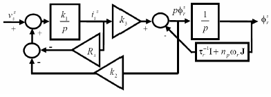
Figure 1: Block diagram of the electrical submodel.
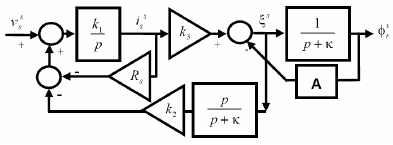
Figure 2: Block diagram of the alternative representation.
In addition, the relationship between the new variable ξs and  is not explicitly dependent on τr (see (7)). As a consequence, it is expected that an estimate of ξs, obtained from stator currents and voltages, will be insensible to τr uncertainty.
III PROPOSED ESTIMATOR
The proposed estimator uses a sliding observer to estimate ξs and a calculator based on Eq. (8) to obtain a rotor flux estimate, according to:
 | (9) |
 | (10) |
 | (11) |
where e =  , represents the estimated value of the rotor flux, sign(x) represents the vector of the signs of x components, K > 0 is a constant, and
  ,
,  , and
, and  stand for assumed values of k1, Rs, and k2, respectively. In addition,
  represents a correction function explained in the next section (see Proposition 3) to be computed as described in section V. Note that the integrator appearing in (9) is not an open-loop integrator, because
  depends on
  . In Fig. 3, the proposed observer block diagram is shown. This estimator works as follows. A value of ξs is estimated from voltage and current measurements (see eqns. (9) and (10)). Note that
  takes discrete values ±K which, as can be proved, make e converge to zero (see Proposition 1 below). By assuming
  = k1,
= k1,  = k2, when the sliding surface is reached (e = 0), the equivalent value of
  ,
,  (Utkin et al., 1999) coincides with the ξs minus a constant c1. This claim will be proven in the next section (see Proposition 2). It must be remarked that ξs estimation is independent of τr, since transfer functions relating
  and ξs do not depend on τr (see Fig. 2). When the sliding surface is reached,
  and the rotor flux estimated with (11) converges to the actual rotor flux value. This is due to the known transfer function between
  and
and  that filters the chattering frequencies.
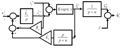
Figure 3: Block diagram of the proposed estimator.
IV ESTIMATOR ANALYSIS: IDEAL CASE
In this section the estimator convergence will be analyzed.
Proposition P1: There is a K > 0 such that e = 0 independently of  ,
,  and
and  .
.
Proof: From eqns. (6)-(8) and (9)-(11) results:
 | (12) |
where
 | (13) |
with  ,
,  and
and  . From (12) results:
 | (14) |
Taking into account the Lyapunov function candidate V = eTe/2 and using (14) results:
 | (15) |
where |x| represents a vector containing the absolute value of x components. Then, if K > sup(|ηs|) then pV < 0 for ||e|| > 0, which proves P1.
From this point on, ideal sliding mode operation will be assumed. Also, the values of k1, Rs and k2 will be considered to be known.
Proposition P2: by assuming  = k1,
= k1,  = Rs and
  = k2 results:
 | (16) |
where → indicates variable convergence after a transient.
Proof: Note that under assumptions in Proposition 2, eqns. (12) and (14) can be written, including the derivative operator in (7) and (9), as follows:
 | (17) |
Then, from (17), if e ≡ 0 then  with c1 a constant. Consequently
  .
.
Proposition P3: if there is a signal  such that
  then, the estimated rotor flux via (11), under the conditions given by P2, satisfies
  .
.
Proof: From P2, by filtering (16) and assuming the sliding surface has been reached (e = 0), the following equation is obtained:
 | (18) |
By using (8), results:
 | (19) |
Since κ can be chosen so that
 | (20) |
then, if a signal  such that
  is available and recalling (11),
 | (21) |
is obtained.
By assuming a signal  is available, it was proved that the estimator given by (9)-(11) allows to estimate the rotor flux after a convergence transient. An algorithm to estimate
  is presented in the next section.
Note that the proposed rotor flux estimator does not use τr. Given the magnetic parameters M, Ls and Lr and the stator resistance Rs, the flux estimation error will converge to zero under ideal sliding mode behaviour. For this reason, the FOC will not lose orientation even if the rotor time constant varies.
In (Derdiyok et al., 2002; Li et al., 2005), low pass filter based techniques were used to compute the equivalent value of the discontinuous signals (for instance, the time derivative of rotor flux estimate). It is wellknown that this method introduces an error, especially when motor is operated at high speed. Note that in our proposal the equivalent value of the discontinuous signal  ,
,  does not need to be computed to obtain
  (see (11)). For this reason, the errors introduced by low pass filtering are avoided.
V COMPUTING 
A procedure for computing  is described below. This procedure is based on the proposal introduced in (Wu and Slemon, 1991).
When the rotor flux is maintained constant by the controller, its geometric locus, in the αβ frame, is (ideally) a circle with center in zero. Taking into account that the actual flux includes odd harmonics, the flux signal should be symmetrical with respect to zero. We define  . Note that eqn. (19) can be written as
  , then the right-hand side describes, in the αβ frame, a circle with center in c1/κ. Consequently, each
  (
( and
and  ) should be symmetrical with respect to an unknown axis given by c1/κ.
In order to obtain  , the maximum and minimum of
  and
and  in the time interval given by two consecutive increasing zero crossings of the signal (see Fig. 4) are obtained and then their mean value is computed. This way,
  results a piecewise constant signal. The described method is used to calculate cα and cβ components at high speed. High speed condition is checked by testing the tz2 − tz1 <Tmax inequality, where Tmax is a fixed time value, and tz2 and tz1 are ascending zero crossing times of
  .
.
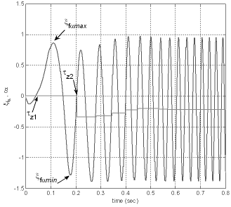
Figure 4:  and cα signals.
The components cα and cβ are computed as follows,
 | (22) |
where  and
and  .
.
Figure 4 illustrates cα computed from (22), where Tmax = 0.1s was selected. We will only refer to cα, since cβ is calculated the same way. Note that the signal  is displaced to a negative value.
VI SPEED AND ROTOR RESISTANCE ESTIMATION
By assuming conditions in P2 are satisfied, it is possible to compute the rotor speed and the rotor resistance with small error (the error produced by a low pass filter). By applying a dq transformation that aligns the d axis with the actual flux  to ξs (eqn. (6)) results:
 | (23) |
 | (24) |
where ()d and ()q are direct and quadrature components expressed in this dq basis, and  . Defining
  (where ()r stands for a rotating reference frame), their estimates (
 and
and  ) are calculated as follows:
 | (25) |
 | (26) |
where
 | (27) |
is a transformation that aligns the d axis with the estimated flux space vector, where  and
and  . The relationships given by (23) and (24) can be used to estimate the rotor speed and resistance replacing the real values by its estimates given in (25) and (26). To estimate Rr, first (23) is written in terms of estimated values and filtered out:
 | (28) |
where LPF is used to indicate a low pass filter applied to remove chattering from high frequencies present in the discontinuous variable ( ),
),  is the nominal value of k2 and
  is the nominal value of Lr. Let
  and
and  . An estimate of the rotor resistance can be found defining the following index:
 | (29) |
and adjusting  in the direction of the negative gradient of J with respect to
  :
:
 | (30) |
where Ka is a constant which determines estimation convergence speed. This estimator is implemented through a simple integrator. Finally, ωr is calculated from (24) as,
 | (31) |
It must be noted that the rotor speed and resistance are slowly varying. For this reason, the errors introduced by the LPF are small.
VII ESTIMATOR ANALYSIS: REAL CASE
In this section the estimator behaviour under parameters uncertainty and nonideal sliding mode operation is analyzed. It is well known that ideal sliding mode operation can not be achieved in practice. However, if the error is bounded, that is, if ||e|| < ε, ε > 0 a constant, then it is possible to quantify the flux estimation error. The next proposition deals with that quantification.
Proposition P4: Under the conditions given in P3, if ||e|| < ε then:
 | (32) |
Proof: From eqn. (17) results:
 | (33) |
Since from (8) and (11),  , then P4 is proved. Then, the flux estimation error is bounded under practical sliding mode operation.
Next, the effect of parameters uncertainty on estimation error is quantified. Including the derivative operator present in (7) and (9), e results:
 | (34) |
where ηs was defined in (13). Like in P2, we have that when e = 0 implies  , with c1 a constant. Replacing in (11),
  by its equivalent value and assuming
  is available the estimated flux becomes:
 | (35) |
From (1), (8) and (13), the following expression is obtained:
 | (36) |
where  , i = 1, 2 and
  .
.
Eqn. (36) specifies the flux estimation error as a function of parameters uncertainty. Note that Δk2 does not affect the estimated flux position, because when Δk1 = ΔRs = 0 the estimated rotor flux angle equals the actual rotor flux angle. The uncertainty in k2 = M/Lr only affects the magnitude of the error. It is also worth noting that k2 is calculated as the quotient of two inductances belonging to the same magnetic circuit. For this reason, in practice this parameter is relatively constant. When the proposed estimator is used in FOC, the orientation will mainly be affected by Rs and k1 = 1/(σLs) uncertainties. Generally, Rs value can be a priori estimated with small error during autotuning (Ben-Brahim et al., 1999). In the field weakening zone k1 will be the parameter which will vary the most.
VIII SENSORLESS CONTROL
The proposed estimator will be used to build a sensorless controller. The block diagram of the control law can be seen in Fig. 5. This block diagram represents a FOC plus a speed PI controller (FOC-PI). The 3/2 block represents the Clarke transformation applied to measured stator currents and voltages. In the VSI block, a PWM signal is synthetized from the reference ( ). The ESTIM block respresents eqns. (9)-(11), (25)-(31) and (22). These equations are used to estimate the rotor flux and speed. Using the estimated rotor flux, the
  block transforms the input variables to a rotating reference frame aligned with
  stands for the stator current in the dq reference frame.
  and
and  references are generated from speed and flux errors, respectively, and two PI controllers included in the closed-loop (see PI3 and PI2). Note that a stator current saturation block has been included in the control loop. Another two PI controllers (PId and PIq) are included to calculate the reference voltage in the dq reference frame. This voltage is transformed to the stationary reference frame by the
  dblock to obtain the VSI block input.
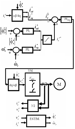
Figure 5: Block diagram of the proposed controller.
IX SIMULATION RESULTS
The proposed sensorless controller was tested by simulation. The model given by (1)-(5) was used to obtain simulation results. Motor parameters, controller gains and initial condition values can be found in Appendix I. In order to describe the inverter behaviour, ideal switches are controlled using a 5KHz triangular signal to build the PWM. The DC bus voltage is 1000V. For the simulations the estimator's parameters were  = k1,
= k1,  = k2 and
  = Rs.
= Rs.
A second order Butterworth filter with a cutoff frequency of 100Hz was used to calculate rotor speed and the estimated rotor resistance(see (31) and (30)). The reference rotor flux ( was set to 1.16Tesla. Figure 6a shows the speed reference and the load torque applied to the motor, whereas in Fig. 6b the rotor speed is drawn. The motor is driven to its nominal speed and applied its nominal torque. As can be seen in these figures, the motor was softly started in order to allow the flux estimator to converge. After the soft start, speed references with greater slopes were imposed (103Hz/sec accelerations). In Fig. 7 rotor speed and rotor flux estimation errors are shown. Figure 8 illustrates the rotor flux amplitude and direct and quadrature stator currents.
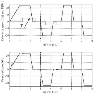
Figure 6: a) Rotor speed reference and load torque. Soft start reference for flux estimation convergence and then, large slope reference (103Hz/sec) for performance test. b) Rotor measured speed. It follows the reference as expected.
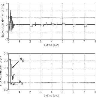
Figure 7: a) Speed estimation error. Large transient up to 1sec due to the estimator convergence b) Flux estimation error. The transient is due to IM's flux initial conditions.
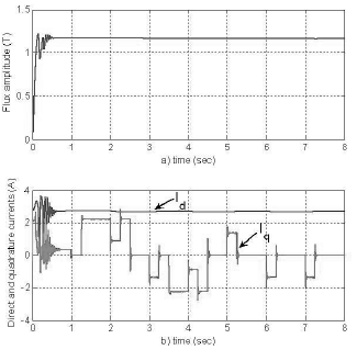
Figure 8: a) Rotor flux amplitude. It converges to the reference nominal flux. b) Direct and quadrature stator currents. Direct current remains constant, since it controls the rotor flux, while quadrature current produces the electrical torque to follow the speed reference.
These simulations were carried out with no parameter mismatch and no current measurement offset. Under these conditions, c is used to correct the constant error produced in the flux estimate by the motor's initial conditions. Once c has reached steady state, there is no further need to update it. The simulations show that the proposed estimator works under these ideal conditions, whereas pure integrator based estimators and low pass filter based estimators do not. The estimator's robustness to measurement offset can not be guaranteed at zero speed, since there is no c update. For this reason, to ensure measurement offset detection and compensation, the proposed estimator should be used at speeds above the threshold speed which triggers c's update algorithm.
In Fig. 9 the Rr estimator is simulated. All model initial conditions were set to zero and the IM was taken to a 10Hz speed. Then, with applied load torque (at 0.3 sec), Rr was varied ±50% from its nominal value. The estimation error in  that appears before the first second of simulation is due to the
  calculation, which converges after 1 second (Fig. 4).
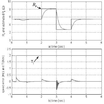
Figure 9: Parameter variation simulation. a) Rr and Rr at a steady speed of 10Hz. b) Load torque an speed error.
In Fig. 10 speed error due to parameter variation is simulated. All initial conditions were set to zero and the IM was driven to a 10Hz speed. Then, with applied load torque (at 0.3 sec), Rs was varied ±5% from its nominal value and afterwards, M was varied ±5% from its nominal value. As can be seen in the figure, Rs variations are partially compensated and though M variations produce a constant speed error, this error is small and bounded.
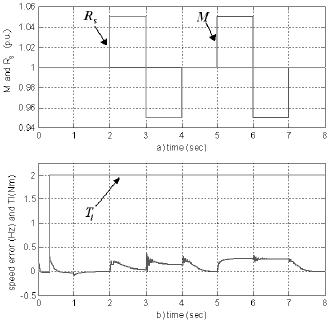
Figure 10: Parameter variation simulation a) Machine Rs and M (per unit) at a steady speed of 10Hz. b) Load torque an speed error.
X CONCLUSIONS
A new sensorless controller for IM has been introduced. The controller uses a FOC law calculated with estimated rotor flux values. These values are obtained via a robust estimator. The estimator also estimates the rotor speed and time constant. Under ideal conditions, the proposed scheme works in the whole speed range. In a real application, where there might be measurement bias and noise, low speeds are limited by the c update algorithm threshold speed.
APPENDIX I
Motor parameters and controller gains are resumed in the following tables.
Plating data

Motor parameters

Initial conditions

Estimator parameters

Controller parameters

ACKNOWLEDGEMENTS
This work was supported by Universidad Nacional del Sur (UNS), ANPCyT and CONICET. J. Solsona is also with CONICET.
REFERENCES
1. Ben-Brahim, L., A. Gastli and M. Aghami, "Auto-Tuning for Sensorless AC Motor Drive Systems,", Proc. of the IEEE Int. Symposium on Industrial Electronics (ISIE'99), 1, 367-372 (1999).
2. Bose, B., Modern Power Electronics and AC Drives, Prentice-Hall (2002).
3. Derdiyok, A., M. G¨uven, H. Rehman, N. Inanc and L. Xu, "Design and Implementation of a New Sliding-Mode Observer for Speed-Sensorless Control of Induction Machine," IEEE Trans. on Ind. Elect., 49, 1177-1182 (2002).
4. Holtz, J., "Sensorless control of induction motor drives," Proceedings IEEE, 90, 1359-1394 (2002).
5. Hurst, K.D., T. G. Habetler, G. Griva and F. Profumo, "Zero-speed tacholess IM torque control: simply a matter of stator voltage integration," IEEE Trans. on Ind. Appl., 34, 790-795 (1998).
6. Li, J., L. Xu and Z. Zhang, "An Adaptive Sliding-Mode Observer for Induction Motor Sensorless Speed Control," IEEE Trans. on Ind. Appl., 41, 1039-1046 (2005).
7. Utkin, V., J. Guldner and J. Xi, Sliding Mode Control in Electromechanical Systems, Taylor and Francis, London, UK (1999).
8. Wu, R. and G. Slemon, "A permanent magnet motor drive without a shaft sensor," IEEE Trans. on Ind. Appl., 27, 1005-1011 (1991).
9. Vas, P., Electrical Machines and Drives, A spacevector theory approach, Clarendon press (1992).
Received: October 18, 2007.
Accepted: February 23, 2009.
Recommended by Guest Editors D. Alonso, J. Figueroa and E. Paolini.


