Servicios Personalizados
Articulo
Latin American applied research
versión impresa ISSN 0327-0793
Lat. Am. appl. res. vol.39 no.3 Bahía Blanca jul. 2009
Non-punctured non-systematic ½-rate turbo codes
J. Castiñeira Moreira, D.M. Petruzzi, M.C. Liberatori and J. C. Bonadero †
† Laboratorio de Comunicaciones, Depto. Electrónica, Facultad de Ingeniería, UNMDP, 7600, Mar del Plata, Arg..
casti@fi.mdp.edu.ar, petruzzi@fi.mdp.edu.ar, mlibera@fi.mdp.edu.ar, jbona@fi.mdp.edu.ar
Abstract — This paper presents non-punctured non-systematic ½-rate turbo codes designed using Finite State Sequential Machines (FSSMs) that operate over the Finite Field GF(4). It is shown that these schemes do not show convergence problems in their iterative decoding, as it happens to similar schemes defined over the binary Field. Non-systematic turbo codes can be useful for the design of communication systems for which error correction and encryption are two important goals.
A relationship is found between the state transitions structure of the FSSM and the BER performance (or equivalently the form of the EXIT chart) of the designed turbo code. FSSMs defined over GF(4) with all-zero input responses of the form of closed cycles are the best options as constituent encoders of non-punctured non-systematic ½-rate turbo codes. A close relationship is also found between the BER performance and the coefficients that define the structure of those FSSMs.
Keywords — Turbo Codes. EXIT Charts. Non-Systematic Coding. Non-Linear Coding.
I. INTRODUCTION
Binary non-systematic turbo codes were introduced by Banerjee et al. (2005). In a non-systematic turbo code, the message symbols are not transmitted, thus only redundancy symbols appear at the output. Non-systematic turbo codes can be defined in any Finite Field of the form GF(q), where usually q=2n, and n is an integer, and the most common definition is done over the Finite Field GF(2), also known as the binary Field. In the classic form of a turbo code (Berrou et al., 1993) the rate of the code is controlled by applying puncturing, which is essentially performed by means of an output selector that transmit only determined output symbols. In this paper we present non-punctured non-systematic (NP-NS) ½-rate turbo codes defined over GF(4).
NP-NS ½-rate turbo codes defined over the binary Field present convergence problems in their iterative decoding, such that for a suitable NS turbo code defined over this Field there is a need of generating three redundancy outputs (by means of the use of three convolutional encoders, or equivalently three Finite State Sequential Machines (FSSMs)) and of applying puncturing over these three outputs to convert the rate of the code from 1/3 to ½ (Banerjee et al., 2005). We show in this paper that the use of FSSMs defined over the Finite Field GF(4) allows us the design of NS ½-rate turbo codes that do not need to apply puncturing. The structure is shown in Fig. 1, and it consists on transmitting simply and alternately the corresponding redundancy outputs of two FSSMs.
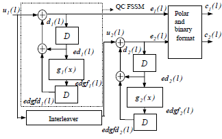
Figure 1. A ½-rate NP-NS turbo code defined over GF(4).
In this paper we will show that in general, NS ½-rate turbo codes present a slight loss in the Bit Error Rate (BER) performance with respect to their equivalent systematic schemes, in the waterfall region of the BER performance curve of the turbo code. However, Banerjee et al. (2005) shows that NS 1/3-rate schemes present lower floor effects in the BER performance curve of turbo codes with respect to their equivalent systematic schemes. We will concentrate our analysis on the waterfall region of the BER performance curve of NP-NS ½-rate turbo codes defined over GF(4).
In spite of their slight loss in BER performance in the waterfall region, NS ½-rate turbo codes can be used in schemes where not only error-control coding, but also privacy is an important additional aim in the design of communications systems. The use of systematic turbo codes is related to the transmission of the message symbols that appear in the transmitted output, allowing a given eavesdropper to directly read this desired information. This is however not strictly speaking a problem in terms of security, because systematic information can be externally protected by applying an encryption algorithm over this message information. In a NS mode, message symbols are not present at the transmitted output, and this increases the levels of privacy with respect to the systematic mode. An application of NS ½-rate turbo codes in secure communication is given in a previous work of the authors (Castiñeira Moreira et al., 2006). A cryptoanalysis (brute force and differential cryptoanalysis) is performed in that paper, for schemes where coefficients of the FSSMs that are constituent encoders of a turbo code are randomly varied during transmission. Under certain conditions, the scheme is shown to be robust against the above described attacks.
II. NON-SYSEMATIC ½-RATE TURBO CODES OVER GF(4)
A. An Encoder of a Non-Systematic ½-Rate Turbo Code
The structure of a NP-NS ½-rate turbo code defined over GF(4) is seen in Fig. 1. The structure has a random interleaver of size L=10000.
The encoder is constructed using FSSMs that operate over GF(4), and include a polynomial g(x) between the two memory units of the FSSM. This polynomial is in general of the form:
 | (1) |
where m is an integer, and ai ∈ GF(q), i=0, 1, ..., m.
Coefficients of this polynomial define the characteristics of the FSSM and also of the turbo code constructed using this FSSM (Castiñeira Moreira et al., 2006). An analysis of the randomness of the output generated by these FSSMs for the all-zero input case is done in Petruzzi et al. (2006). Output randomness and the state transition structure of the all-zero input response of the FSSM define the behaviour of the NS ½-rate turbo code constructed with that FSSM.
We will consider all the possible turbo codes defined over GF(4), with s=2 memory units, and with polynomials of degree m=2 or less, of the form g(x)=a0+a1x+a2x2. The turbo code is always constructed using the same FSSM in both constituent encoders. Thus, a given NP-NS ½-rate turbo code defined over GF(4), and with m=2, will be denoted as an (a0 a1 a2) NP-NS ½-rate turbo code. Therefore, for each turbo code (Fig. 1),
 | (2). |
B. Structure of the state transitions of FSSMs over GF(4)
In this paper we analyse the state transitions structure of the 63 cases of FSSMs defined over GF(4) with s=2, and g(x)=a0+a1x+a2x2, and its relationship with the BER performance of the corresponding NP-NS ½-rate turbo code. A similar analysis is done in Petruzzi et al. (2007) for systematic turbo codes. The use of these FSSMs provides a wider range of possibilities of turbo coding schemes in comparison with those defined over the binary Field. This number of possibilities increases as m and n increase.
FSSMs under analysis show different responses to the all-zero input, which are essentially determined by the so called current state - next state representation. FSSMs used in this paper are non-linear, and they have a non-zero output for the all-zero input.
For each FSSM we have analysed the response for the 16 possible initial state conditions. Responses of FSSMs under analysis can be classified into different groups. FSSMs can show responses that are cycles, which can be run in a closed form or not. Since this difference in the behaviour of the FSSM is relevant to its performance as a constituent encoder of a turbo code, we want to differentiate these two types of cycles. A cycle that includes always a given set of states and is run starting from any of these states, will be referred to as a closed cycle. The number of states that the cycle runs is the length of the cycle, and it will be denoted as Lc. When the cycle is reached after a sequence of states that do not form the cycle, showing a transient behaviour, the response will be referred to as a cycle with transients, and the number of states of the cycle (excluding the number of states of the transient) is the length of the cycle, denoted as LT . FSSMs can also show responses without cycles, and also stationary responses, which can be given at the all-zero state, or at other non-zero states.
A coefficient is defined in Petruzzi et al. (2007) that measures the randomness and properties of the state transitions structure of FSSM and their relationship with the BER performance of the corresponding turbo code. It is called the random behaviour coefficient ΔR, and its definition is repeated here for clarity:
 | (3) |
where Lc(i) is the length of the closed cycle present at the response for the initial condition i, ηδ(i) is the delta function coefficient measured for the all-zero input case for the initial condition i, which was defined in Petruzzi et al. (2006), and evaluates the response of the auto correlation of the output of the FSSM for the all-zero input, and Lc_max is the maximum length of a closed cycle verified for the corresponding FSSM, evaluated over all the responses. If the response has cycles with transients, or responses without cycles for the initial condition i, then we set Lc(i)=1. When the response is a closed cycle, Lc(i) can adopt any value in the set {2,3,4,6,15}. The addition in (3) excludes stationary responses and all-zero outputs.
This coefficient is evaluated over the 16 responses of the FSSM by calculating a weighted average of the delta function coefficient ηδ for each response. The weight is the length of the closed cycle (if any) present at that response. It is found that the higher is the value of the random behaviour coefficient of the FSSM, the better is in general the BER performance of the NP-NS ½ rate turbo code constructed with that FSSM.
III. EXIT CHART AND BER PERFORMANCE OF NON-PUNCTURED NON-SYSTEMATIC TURBO CODES OVER GF(4)
A. BER performance analysis of non-punctured non-systematic turbo codes over GF(4)
The performance of a turbo code can be analysed by using two well known procedures. One of them is the simulation of the Bit Error Rate, by depicting a curve of this parameter as a function of the average bit energy-to-noise power spectral density ratio, Eb/N0. Another tool for analysing the behaviour of iteratively decoded codes like turbo and LDPC codes has been proposed in Ten Brink (2001). He introduced a very useful tool that is known as the Extrinsic Information Transfer (EXIT) chart. The EXIT chart is an especially good tool for the analysis of the waterfall region, and also illustrates the behaviour of the code in the other two regions of the BER performance curve of a turbo code (Hanzo et al., 2001; Castiñeira Moreira and Farrell, 2006). It describes, for each value of Eb/N0, the relationship between the mutual information of the a priori information and the message bit information, IA, and the mutual information of the extrinsic information and the message bit information, IE This Extrinsic Information Transfer function is defined as (Ten Brink., 2001):
 | (4) |
Similarly, an EXIT chart can also describe the mutual information IA as a function of the mutual information IE, which can be useful for understanding the process in which the extrinsic information of the current iteration becomes the a priori information of the following iteration (Ten Brink , 2001).
This analysis is applied to NP-NS ½-rate turbo codes designed in this paper using the proposed FSSMs under study. Some relationship is found between the EXIT chart appearance and the structure of the state transitions and randomness of the output for the all-zero input case, quantitatively indicated by the value of the defined random behaviour coefficient ΔR.
On the other hand the classic BER performance analysis can be also used to characterise these turbo codes. It is found that NP-NS ½-rate turbo codes over GF(4) have the best BER performance when they are constructed using FSSMs that have the highest values of the random behaviour coefficient, which means that the all-zero input responses of these FSSMs are of the form of long (in some cases the longest) closed cycles. Turbo codes constructed using FSSMs with cycles with transients perform worse than those with closed cycles. This can be verified in Fig. 2, where BER performances of several NP-NS ½-rate turbo codes are shown. Simulations are done for the transmission of 250 blocks of 10000 elements of the Finite Field GF(4), encoded by using in all the cases the same random interleaver of size L=10000, decoded using the LOG-MAP BCJR decoder (Bahl et al., 1974), with 8 iterations.
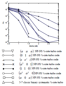
Figure 2. BER performance curves of several NP-NS ½ rate turbo codes over GF(4).
The best schemes among those shown in Fig. 2 are the NP-NS ½-rate (α 0 α) turbo code (ΔR=0.5058) and the NP-NS ½-rate (α2 α2 0) turbo code (ΔR=0.7260), that show high values of the random behaviour parameter.
These schemes use FSSMs that have closed cycles of length 6 and 15 respectively. BER performances of these schemes are quite close to that corresponding to one of the best binary systematic schemes. Floor effect is not present in this particular simulation for these two schemes. The simulation involves the transmission of 5×106 bits. Best schemes seen in Fig. 2 have presented no errors in this simulation, for Eb/N0=2, 2.5 and 3dB. This could indicate that the measured BER in these cases is less than Pbe<2×10⁻⁶. We should note however that reliable values of the BER obtained by simulation require that the number of errors present in the simulated case has to be at least one hundred o larger. This means that BER performances seen in Fig. 2 are reliable only for Pbe>10-5. This is however enough for our purposes, because we analyse the waterfall region of the BER performance, typically present in the range 10-1>Pbe>10-5. The comparison is done with respect to a systematic binary turbo code considered as that with the best BER performance possible. As mentioned earlier, NP-NS ½-rate binary turbo codes present convergence problems and show very poor BER performances, and it is not useful to consider them in this comparison.
B. EXIT chart analysis of non-punctured non-systematic turbo codes over GF(4)
A strong relationship is found between the state transitions structure and randomness of the output of the FSSM for the all-zero input, and the appearance of the EXIT chart of the corresponding turbo code, in the case of ½-rate systematic turbo codes over GF(4) in (Petruzzi et al., 2007).
We can classify FSSMs in terms of their state transitions structures. There are essentially two groups of FSSMs, which will be called groups A and B. In each group, we can also identify slight differences that are described in the form of subgroups. Groups A and B differ not only in the length of the cycle but also in the type of cycle of the response for each initial condition. Group A is constituted of FSSMs for which the 15 recycles, in some cases of the maximum length, in some other cases of considerable long length, and there is always only one stationary response. FSSMs of this group are those that provide the corresponding non-systematic turbo code with the best BER performance, among all the 63 cases under study. They are also FSSMs with the maximum values of the random behaviour coefficient ΔR.
A second group is called group B, and in this group not all the all-zero input responses are of the form of closed cycles. Some responses are of the form of cycles with transients, and sometimes there are no stationary responses, or there is more than one stationary response. The random behaviour coefficient of schemes of this group is always less than ΔR <0.3.
A strong relationship is found between the state transitions structure and the form of the EXIT chart for schemes of the so called group A, for NP-NS ½-rate turbo codes. However, this correspondence is not clearly given for schemes of group B. Especially in the case of group B, the form of the EXIT chart of a NP-NS turbo code is rather defined by the values of coefficients a1 and a2. NP-NS ½-rate turbo codes that belong to group A, show slight differences in the corresponding EXIT charts. These schemes are the NP-NS ½-rate turbo codes with the best BER performances, that is, those that show the best EXIT charts. Sub group A.1, characterised by having FSSMs with the longest closed cycles (Length Lc=Lmax=15) have EXIT charts of the form of Fig. 3.
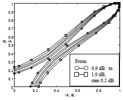
Figure 3. EXIT chart of the NP-NS (α2 α2 0) ½-rate turbo code.
Very similar EXIT charts are found for all the other schemes of the sub group A.1, that are the NP-NS ½-rate turbo codes for which a0=0,1,α,α2, a1=α,α2 and a2=0. A second sub group, called A.2, is constituted of turbo codes with FSSMs that have 15 responses to the all-zero input of the form of closed cycles, 12 of length Lc=6, 3 of length Lc=3, and one stationary response. This sub group is constituted of NP-NS ½-rate turbo codes for which a0=0,1,α,α2, a1=0 and a2=1,α,α2. In this sub group, NP-NS ½-rate turbo codes for which a0=0,1,α,α2, a1=0 and a2=α perform better than those for which a0=0,1,α,α2, a1=0 and a2=1,α2. The set of schemes for which a0=0,1,α,α2, a1=0 and a2=α shows a higher minimum distance between the shortest all-zero input responses (those with Lc=3) with respect to the set of schemes for which a0=0,1,α,α2, a1=0 and a2=1,α2. This indicates differences between the corresponding trellis structures, which are closely related to the values of coefficients a1 and a2.
An example of the sub group A.2 is the (α 0 α) NP-NS ½-rate turbo code (ΔR=0.5058) whose BER performance is seen in Fig. 2. Figure 4 shows the EXIT chart for this turbo code.
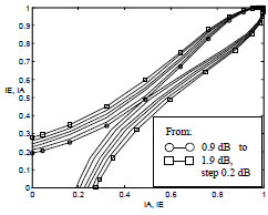
Figure 4. EXIT chart of the NP-NS (α 0 α) ½-rate turbo code.
The "bottleneck" region of the EXIT chart is identified as a region in which iterations play an important roll in the efficiency of the iterative decoding of these codes (Ten Brink, 2001). Figures 3 and 4 show quite similar EXIT charts, which correspond to the best NP-NS ½-rate turbo codes.
The third sub group in group A is the sub group A.3, constituted of NP-NS ½-rate turbo codes for which a0=0,1,α,α2, a1=1 and a2=0. Schemes of this sub group perform worse than those of sub groups A.1 and A.2. The BER performance of the (1 1 0) NP-NS ½-rate turbo code that belongs to sub group A.3 is seen in Fig. 2. Its Exit chart is shown in Fig. 5.
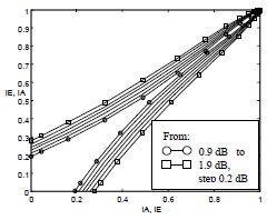
Figure 5. EXIT chart of the NP-NS (1 1 0) ½-rate turbo code.
An undesirable characteristic of an EXIT chart, depicted for a given value of Eb/N0, is the presence of what we call anticipated intersecting points. An anticipated intersecting point is one for which the curve IE=Tr(IA, Eb/N0) intersects the curve IA=Tr(IE,Eb/N0) before the point IE=Tr(IA, Eb/N0)= IA=Tr(IE,Eb/N0)=1.
In this sense, group A presents no anticipated intersecting point in the simulated range for the EXIT charts of its NP-NS ½-rate turbo codes.
There is however a close relationship between the form of the EXIT chart and the set of coefficients of g(x), {a1,a2} especially for schemes of group B. In this group, NP-NS ½-rate turbo codes of relatively quite good BER performances are those for which a0=0,1,α,α2, a1=α and a2=α2 and a0=0,1,α,α2, a1=α2 and a2=1. One of these schemes is the (α α2 1) NP-NS ½-rate turbo code, whose BER performance is seen in Fig. 2. Its Exit chart is shown in Fig. 6.
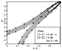
Figure 6. EXIT chart of the NP-NS (a a2 1) ½-rate turbo code.
Exit charts of Figs. 5 and 6 look quite similar. Slight differences in the shape of the EXIT chart justify correspondingly differences in the BER performance. NP-NS ½-rate turbo codes with the worst BER performance, or equivalently with the worst EXIT charts, belong also to group B. These are the NP-NS ½-rate turbo codes for which a0=0,1,α,α2, a1=α,α2 and a2=α, and also for which a0=0,1,α,α2, a1=α,α2, and a2=α. The (α α α) NP-NS ½-rate turbo code (ΔR=0.2977) is representative of this sub group, and its BER performance is seen in Fig. 2. The corresponding EXIT chart is shown in Fig. 7. FSSMs used in this sub group shows all-zero input responses that sometimes are of the form of closed cycles of lengths Lc=3 and Lc=6, and some other times are of the form of cycles with transients of lengths LT=3 and LT=6. The presence of responses of the form of cycles with transients identifies NP-NS ½-rate turbo codes of rather poor BER performances. This is coincident with the existence of anticipated intersecting points in the corresponding EXIT charts, as seen in Fig. 7. Schemes of this sub group present EXIT charts with anticipated intersecting points at Eb/N0=0.9, 1.1, 1.3 dB, and sometimes also at Eb/N0=1.5 dB.
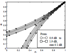
Figure 7. EXIT chart of the NP-NS (α α α) ½-rate turbo code.
In general schemes of group B never reach the optimum performance for NP-NS ½-rate turbo codes, which are verified for schemes that belong to group A. These are those characterised by all-zero input responses of the corresponding FSSM of the form of closed cycles, and also by having the highest values of the random behaviour parameter ΔR.
IV. CONCLUSIONS
EXIT chart analysis performed in section III indicates that the use of FSSMs defined over GF(4) allows us the design of NP-NS ½-rate turbo codes that do not show convergence problems in their iterative decoding, as happens to the same schemes defined over the binary field GF(2). The inclusion of the polynomial g(x) in the structure of the FSSM, both operating over GF(4), provides much more cases of study than in the case of the binary field, allowing a deeper analysis of this type of turbo codes. Non-systematic schemes can be useful for applications where also encryption is an important goal of the design. The best proposed schemes perform with a loss in BER performance that is less than 0.5dB with respect to the best known binary systematic turbo codes. This loss is also present between a given (a0 a1 a2) NP-NS ½-rate turbo code and its systematic version, in general terms.
Since message symbols are "hidden" in the non-systematic case, this on one side improves the encryption properties of the transmission, but on the other side is in a trade-off with the BER performance. The loss is however acceptable in practical applications.
Schemes that belong to group A are those with the best performance. These schemes use FSSMs with all-zero input responses that are always of the form of closed cycles, excepting the stationary response, and also have random behaviour coefficients that are always higher than ΔR>0.40. In this group there is a relatively strong correspondence between the state transitions structure of the FSSM, and the form of the EXIT chart of the corresponding turbo code. This correspondence is however stronger in the systematic case than in the non-systematic case. This correspondence is more clearly given between the form of the EXIT chart and the set of coefficients {a1,a2}. This trend is even more evident in group B.
REFERENCES
1. Bahl, L., J. Cocke, F. Jelinek and J. Raviv, "Optimal decoding of linear codes for minimising symbol error rate," IEEE Transactions on Information Theory, 20, 284-287 (1974).
2. Banerjee, A., F. Vatta, B. Scanavino and D. J. Costello, "Nonsystematic Turbo Codes," IEEE Trans. on Comm., 53, 1841-1849 (2005).
3. Berrou, C., A. Glavieux and P. Thitimajshima, "Near Shannon limit error-correcting coding and decoding: turbo codes," IEEE International Conference on Communications, Geneva, Switzerland, 1064-1070 (1993).
4. Castiñeira Moreira, J. , D.M. Petruzzi, M.C. Liberatori, and B. Honary, "Trellis hopping turbo coding," IEE Proceedings - Communications, 153, 966-975 (2006).
5. Castiñeira Moreira, J. and P.G. Farrell, Essentials of Error-Control Coding, John Wiley and Sons (2006).
6. Hanzo, L., T.H. Liew and B.L. Yeap, Turbo Coding, Turbo Equalisation and Space-Time Coding, for Transmission over Fading Channels, IEEE Press, Wiley (2001).
7. Petruzzi, D.M., J. Castiñeira Moreira and D.G. Levin, "Quasi-Chaotic coding over GF(q)," IEEE Transactions on Communications, 54, 462-468 (2006).
8. Petruzzi, D.M., M.C. Liberatori, J.C: Bonadero and J. Castiñeira Moreira, "Non-linear turbo coding over GF(4)," XII RPIC, Rio Gallegos (2007).
9. Ten Brink, S., "Convergence behaviour of iteratively decoded parallel concatenated codes," IEEE Trans. On Comm., 49, 1727-1737 (2001).
Received: October 18, 2007.
Accepted: July 2, 2008.
Recommended by Guest Editors D. Alonso, J. Figueroa, E. Paolini and J. Solsona.


