


Servicios Personalizados
Articulo
 pdf en Inglés
 Articulo en XML
 Referencias del artículo
 Permalink
Latin American applied research
versión impresa ISSN 0327-0793
Lat. Am. appl. res. vol.39 no.3 Bahía Blanca jul. 2009
Block-based transceivers for frequency selective channels with reduced redundancy
L. Rey Vega† and C.G. Galarza†
† CONICET and Facultad de Ingeniería, U.B.A., Paseo Colón 850, Buenos Aires, Argentina lrey@fi.uba.ar, cgalar@fi.uba.ar
Abstract — We propose a transceiver structure for a frequency selective channel that allows the introduction of reduced redundancy. We optimize jointly the transmitter and receiver in this structure to maximize the information rate. The simulation results show that the proposed design has good performance while increasing the bandwidth efficiency.
Keywords — Block Transceivers. Intersymbol Interference (ISI). Redundancy. Interblock Interference (IBI). Mutual Information.
I. INTRODUCTION
Time invariant single-input-single-output (SISO) communication channels have been studied for a while already. However, the problem of achieving high transmission rates under limited computational resources has not been completely solved yet. For instance, block-by-block communication systems have shown to be efficient schemes for transmitting over inter-symbol interference (ISI) channels (Lechleider, 1990; Scaglione et al., 1999b; Lin and Phoong, 2000). Examples of block-by-block communication systems are orthogonal frequency division multiplexing (OFDM) and discrete multitone modulation (DMT) (Chow et al., 1991). In a block-based system, transmitter and receiver act on a block-by-block basis and redundancy is added to each block in order to remove inter-block interference (IBI). However, the introduction of redundancy leads to a worse bandwidth efficiency. Although this concern is immaterial for large symbol block sizes, smallsized blocks are still worthy to avoid large decoding delays and computational complexity. In the past, ISI free multirate FIR filterbank transceivers with reduced redundancy have been obtained by Lin and Phoong (2002). However, these solutions may not lead to a block-by-block communication system. Although necessary conditions for the existence of a parameterization for all block-by-block ISI free transceivers with reduced redundancy have been derived by Lin and Phoong (2002), a sufficient condition is still lacking.
In this paper we propose a family of transceivers with reduced redundancy that is obtained by controlling the IBI. Also, we derive all the transceivers that maximize the information rate subject to a contraint of maximum transmit power.
The notation is as follows: boldfaced lower-case letters represent vectors and boldfaced upper-case letters are reserved for matrices. The notation AT represents the transpose of A. The notations IM×M and 0M×N represent the M × M identity matrix and M × N null matrix respectively. Also |A| and |A|F denote the determinant and the Frobenius norm of matrix A. The notation  stands for the ceiling operation on real numbers and I(x; y) is the mutual information between random variables x and y.
II. PROBLEM STATEMENT
Let hn be the discrete time impulse response of the SISO channel. We assume that hn is a linear time invariant (LTI) system with finite impulse response (FIR) of length L + 1. We analyze the problem of sending and receiving blocks of N samples. For that, the vectors s(n) = [snN snN−1 ... snN−N+1]T, and y(n) = [ynN ynN−1 ...ynN−N+1]T represent the n-th blocks sent and received through the channel. Then, assuming that L + 1 < N, the IBI is limited to two consecutive blocks only and y(n) is expressed as
 | (1) |
where v(n) ∈  is the n-th block of additive noise at the output of the channel, H1 ∈
  , and H2 ∈ . In particular, H1 is upper triangular Toeplitz whose first row is [h0 ...hL ... 0] ∈ . Similarly, H2 is lower triangular Toeplitz whose first column is [0 ...hL ...h1]T ∈ . Finally, we consider
 | (2) |
where x(n) = [xnM xnM−1 ...xnM−M+1]T is the nth transmitted block formed by M symbols,  is the n-th estimated block, A ∈
  is the transmit matrix, and B ∈
  is the receive matrix.
Well-known transceiver structures as the zeropadding (ZP) (Lin and Phoong, 2002; Lin and Phoong, 2001; Scaglione et al., 1999a,b) and the cyclic prefix (CP) technique (Chow et al., 1991) may be formulated under this framework. For instance, when using ZP with leading zeros, N = M + L and the first L rows of the transmit matrix A are zero. It is also possible to define matrices A and B to include a prefix of length L when using the CP technique (Lin and Phoong, 2000). In general, N > M and Q := N − M is the redundancy that helps to remove the IBI inherent to any block-based transmission system. Although redundancy may be beneficial (Scaglione et al., 1999b), it uses more bandwidth because more symbols have to be transmitted in a given period of time. If T is the signaling period, then the actual transmission rate is (M + Q)/MT , leading to an excess bandwidth of Q/MT due to the redundancy. Our goal is to build a structured redundancy to improve the bandwidth use without decreasing the amount of information transmitted per block, i.e., to improve the bandwidth efficiency. We replace (2) into (1) to obtain
 | (3) |
We see that for dispersive channels IBI between successive blocks cannot be avoided if no particular structure is imposed onto the transceiver. For example, the structure of a ZP transceiver is such that the product H2A in (3) vanishes and the interfering term disappears. Notice that techniques such as ZP or CP utilize a redundancy length Q = L. It is clear that large values of L lead to a significant decrease in the information rate that may be compensated by augmenting the block length. However, by increasing the block length we are also increasing the decoding delay and the computational load. Therefore, a tradeoff between computational requirements and bandwidth efficiency is set up. In next section, we propose to transmit a redundancy smaller than L by controlling the IBI, not by suppressing it. In particular, we pose the structure of a transceiver and we design its component so that the average mutual information per sample between the transmitted symbols and the received ones, or the information rate, is maximized.
III. TRANSCEIVERS WITH REDUCED REDUNDANCY
We assume that complete channel state information (CSI) is available at the transmitter and receiver and that the channel remains invariant at least for the duration of a block. On a first approach, the symbols xn are zero-mean, uncorrelated continuous random variables, i.e. coming from a constellation with infinitesimal granularity. We defer for later the case of symbols taken from finite alphabets. Under these assumptions, 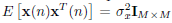 . The noise vn is assumed to be Gaussian and zero-mean. The noise autocorrelation matrix is given by E [v(n)vT(m)] = Rvvδnm, where δnm is the Kronecker function. Finally, the noise and the symbols are uncorrelated, i.e. E [x(n)vT(m)] = 0M×N, ∀n, m, where N = M + Q.
A. Structure of the transceivers
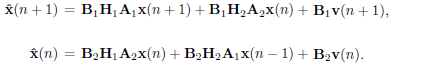
Suppose that two transceivers, (A1, B1) and (A2, B2), are available. Then, we will use them in an alternating way on two successive blocks as follows:
 | (4) |
This structure may be thought of as a periodic block transceiver where the two pairs of transmitters and receivers act in an alternating way. Figure 1 shows the operation of this structure. The block of data x(n) is processed by A2 before being sent through the channel. At the receiver, the signal block y(n) is multiplied by the receive matrix B2. Then, next block of data x(n + 1) is processed by the transmit matrix A1, and the corresponding block y(n + 1) is received by B1. The same process is repeated on the following block using A2 and B2, and so on.
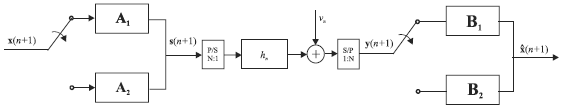
Figure 1: Transceiver structure: the blocks in the transmitter are converted to a serial stream before entering the channel; at the receiver, the serial stream is converted into blocks of N samples. In a synchronous way, the switch at the transmitter acts on each block of M symbols, and the switch at the receiver acts on each block of N samples.
Clearly, model (4) does not lead to an optimum solution if one would want to maximize the average mutual information. An optimum structure would consider joint spectral shaping and decoding of successive blocks of symbols to account for the IBI terms. However that structure would have large computational complexity. Instead, model (4) entails block by block coding and decoding operations. Still, the effect of the IBI terms can be controlled by carefully selecting the pairs (A1, B1) and (A2, B2).
Following the line of thought of Lin and Phoong (2003), it can be proved that if the redundancy length satisfies that  , it is possible to eliminate the IBI term B1H2A2x(n). Select B1 and A2 as
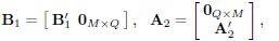 | (5) |
where  and
and  are M × M matrices, and (5) corresponds to ZP for
  using Q < L zeros. Then,
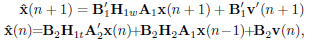 | (6) |
where v'(n) is a length M vector obtained from v(n) by removing its last Q entries, H1w is a M × N matrix obtained by removing the last Q rows from H1, and H1t is a N × M matrix obtained by removing the first Q columns from H1. Notice that by using (5), the IBI term on is eliminated. Moreover, the energy of the IBI term on , namely B2H2A1x(n − 1), may be controlled with a judicious choice of B2 and A1. In the next subsection we will maximize the information rate for this choice of tranceiver structure.
B. Optimization of the transceivers
We want to maximize the information rate for two consecutive blocks of symbols when a bound is imposed on the total power transmitted by these two blocks. For that, define the average mutual information per sample as
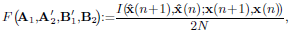 | (7) |
where we have emphasized the dependence of the objective function on the transceivers. We are now in conditions to set up the optimization problem:
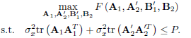 | (8) |
The restriction on the total power of s(n + 1) and s(n) allows for an unequal power distribution between consecutive blocks. In principle this is better than assigning equal power to both output blocks, since they are not facing the same channel, as it is shown in (6).
Before solving problem (8), let us analyze the structure of the mutual information  when (5) is used. First, recall that v'(n + 1) and v(n) are uncorrelated vectors, and the components of x(n) are uncorrelated in time and uncorrelated with v(n). Now, using the definition of mutual information (Cover and Thomas, 1991) we can show that:
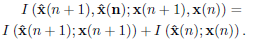 | (9) |
Let us define the equivalent noise terms in (6) as z1(n) :=  and z2(n) := B2v(n) + B2H2A1x(n − 1), and their autocorrelation matrices as
  and
and  . Because the noise vn is assumed to be Gaussian and independent of the input symbols xn, and assuming that xn are zero-mean and uncorrelated, the mutual information terms in the RHS of (9) are maximized when x(n + 1) and x(n) are Gaussian random vectors with autocorrelation matrix
  (Cover, 1991). Then, it can be shown that
 | (10) |
 | (11) |
Notice that equations (10) and (11) are effectively coupled by that is parameterized by A1 and B2. This coupling represents the effect of the IBI on the information rate of the block system. Block x(n − 1), which is spectrally shaped by the matrix A1, acts as an interference source for block x(n). As this interference is included in z2(n) and hence in its autocorrelation , equations (10) and (11) cannot be solved separately.
Hadamard's inequality (Cover, 1991) implies that (7) is maximized when the arguments of the determinants in (10) and (11) are simultaneously diagonalized. Thanks to the structure assumed in (5), simultaneous diagonalization is possible. Otherwise the optimization problem would be more difficult. Now, following to Scaglione et al. (1999a) we choose A1 and in the following manner
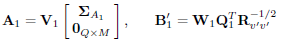 | (12) |
to diagonalize the argument of (10). In the previous equation, W1 is an arbitrary M × M invertible matrix,  is the autocorrelation matrix of v'(n + 1),
  is a M × M diagonal matrix with positive entries, and V1 and Q1 are N × N and M × M orthonormal matrices given by the following singular value decomposition:
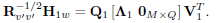 | (13) |
Here,  has dimension M × M and its entries along the diagonal are all positive. Similarly, the argument of (11) is diagonalized when
 | (14) |
As before, W2 is an arbitrary and invertible M × M matrix, and  is a diagonal matrix with positive entries. Now,
  , and V2 and Q2 are M × M and N × N orthonormal matrices given by the following singular value decomposition:
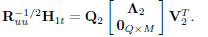 | (15) |
Once again, the diagonal matrix  has dimension M × M and its entries along the diagonal are positive. Using the expression of A1 in (12) and the definition of Ruu we can express (15) as
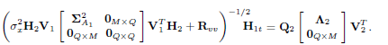 | (16) |
Then, replacing (12) and (14) into (8) the optimization problem is re-formulated as
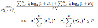 | (17) |
where 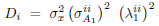 and
and 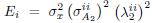 . Equation (17) shows that given the parameters
  the set of solutions
  , is obtained by the classical water-filling solution (Cover, 1991) for 2M parallel Gaussian channels. However this solution implicity assumes that
  and
and  do not depend on
  . While this is true for it is not true for , which is a function of
  as it can be deduced from (16). Also from (13) and (16) it can be seen that V1 and Q1 are independent of while V2 and Q2 depend on . To obtain a close form solution for problem (17) we need to formulate the functional dependence among the elements and
  . Unfortunately, this is not possible in general.
For that reason we have to turn to an algorithmic approach. For instance, using the channel knowledge, we solve (13) to obtain V1, Λ1 and Q1. Then, using , we formulate the following problem:
 | (18) |
The solution to this problem is obtained by using wellknown algorithms (Scaglione et al., 1999a). In next step we use V1 and to solve (16) for V2, Λ2 and Q2. Now, with the values of  and
and  already obtained, we solve problem (17). The result is a new set . We iterate on the procedure by inserting the new values of
  into (16), computing a new singular value decomposition, and solving the water-filling problem (17). The procedure is repeated until a stop condition is met. The algorithm is summarized below:
Algorithm 1
- Initialization: set k = 0. Compute V1, Λ1 and Q1 using (13). Solve problem (18). Generate
 . Set k = 1.
 - Compute
 ,
,  and
and  using (16) and
  .
. - With Λ1 and solve the water-filling problem (17). Construct
 and
and  .
. - If
 , where ε > 0 is a predefined threshold, take
  ,
,  ,
,  ,
,  , and exit. Otherwise, set k = k + 1 and go to step 2).
The convergence of the algorithm outlined above was tested with numerical experiments. It was interesting to note that for a large number of channels and thresholds , one or two iterations were enough for convergence.
IV. DISCUSSION
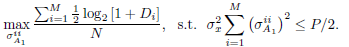
The derivation presented above contains certain details that are worth discussing further. For instance, it is possible to formulate a simplified but suboptimal version of the optimization problem (8). For that, the condition on the total power, would be replaced by an equal bound on the output power on both blocks of symbols x(n + 1) and x(n), i.e.,  and
and  . This formulation may be relevant during implementation because it would guarantee that the average output power is always below a specified maximum output power. In addition, an iterative procedure for obtaining
  and
and  is no longer needed, and we can set the following procedure:
Algorithm 2
- Compute V1, Λ1 and Q1 using (13). Solve problem (18). Generate
 .
. - Use in (16) for determining V2, Λ2 and Q2.
- Obtain the water filling solution for
 , which is achieved by solving problem (18) for , with Ei replaced by Di.
On a different item, recall that after imposing structure (5), we had to obtain the pairs and that solve problem (8). From (12) we know that the pair is determined up to the choice of an invertible matrix W1. Similarly, we need to select W2 to define the second pair . It is clear that W1 and W2 can be exploited to impose additional properties to the transceivers. For example, following the ideas by Scaglione et al. (1999a), we can obtain Zero-Forcing (ZF) and Minimum Mean Square Error (MMSE) receivers. It can be proved that these two choices lead to a transmission over M parallel independent channels, i.e., symbol by symbol detection within a block is optimal.
Finally, notice that the results given above are valid for Gaussian signaling. However, when the symbols xn come from a finite alphabet we can use the gap approximation (Cioffi et al., 1995). The gap Γ is defined so that the number of bits to be transmitted by the i-th channel is:
 | (19) |
Here, SNRi = Di or SNRi = Ei depending on which transceiver pair we are considering. The choice of Γ depends on the maximum allowable symbol error rate and on the particular constellation for the i-th sub-channel. For example if we assume that all subchannels use a PAM constellation, then the margin can be chosen as:
 | (20) |
where  is the maximum symbol error rate permitted in any of the sub-channels (we could also set different symbol error rates and margins for each subchannel) and erfc−1(·) is the inverse of complementary error function. Obviously the size of the PAM constellations for each sub-channel will be different depending on SNRi. As pointed out by Scaglione et al. (1999a), the gap can be reduced relying on codification on each sub-channel.
V. SIMULATION RESULTS
We have performed numerical experiments with the algorithms introduced in previous sections. In this section, we present the results obtained by comparing our scheme with the ZP with leading zeros approach presented by Scaglione et al. (1999a) and with the DMT scheme. We define
 | (21) |
where P is the average output power for two blocks of symbols, M is the number of symbols per block and  is the noise variance. The noise is assumed to be white, i.e.
  and
and  . In the case of the DMT scheme and the one by Scaglione et al. (1999a) this definition of SNR is valid if we think P/2 as the average output power per block of symbols.
First we consider the following impulse response channel: [1, −0.3, 0.5, −0.4, 0.1, −0.02, 0.3, −0.1]. In this case L = 7 and we will consider for our scheme Q = 4. For the scheme by Scaglione et al. (1999a) and the DMT scheme, the redundancy included is Q = 7.
In Fig. 2 we show the information rates (in bits per samples) as functions of SNR. Our scheme outperforms the one presented by Scaglione et al. (1999a) as well as DMT for small and large block sizes (M = 16 and M = 64). However, it is clear that for larger block sizes the gain in performance is reduced. We also show the performance of the suboptimal procedure given in algorithm 2. It is clear that this suboptimal solution performs as well as the optimal one. In Fig. 3 we show the information rate gain of the scheme proposed in this paper over the DMT scheme an the one by Scaglione et al. (1999a) as function of the maximum allowable symbol error rate. In this case we use equation (19) for assigning the number of bits bi ∀i = 1,...,M. In this case the channel used was [0.1659, 0.3045, −0.1159, −0.0773, −0.0015] which was drawn from an ADSL environment (Lin and Phoong, 2002). Here, L = 4, and Q = 2 for the proposed scheme and Q = L = 4 for the DMT scheme and the one by Scaglione et al. (1999a). We have used algorithm 2 for deriving our transceivers. We see that the gain in information rate for the proposed scheme is about 10 − 12% over the DMT and the scheme by Scaglione et al. (1999a).
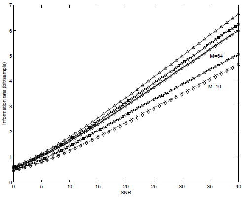
Figure 2: Channel capacity and information rates in bits per sample as functions of SNR for M = 16 and M = 64. Legend:  : channel capacity; o: scheme proposed (algorithm 1);
  : scheme proposed (algorithm 2); ×: scheme proposed by Scaglione et al. (1999a);
  : DMT.
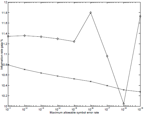
Figure 3: Information rate gain for the proposed scheme over the DMT scheme and the one proposed by Scaglione et al. (1999a) as function of the maximum allowable symbol error rate. SNR=10 dB and M = 16. Legend: o: gain of the proposed scheme over DMT; ×: gain if the proposed over the one by Scaglione et al. (1999a).
As pointed out by Scaglione et al. (1999b) a block transmission system can be thought of as a multirate filterbank system. Bearing this idea in mind we can think A1 and A2 as being banks of M filters, where the impulse responses of each of these filters are the columns of the matrices A1 and A2. Following Scaglione et al. (1999b), the average spectral magnitude of the transmit filter is defined as:
 | (22) |
where Ai(f) is the Fourier transform of the i-th column of matrix A. This average spectral magnitude gives an idea on how the transmit power is distributed in frequency.
In Fig. 4 we show the average spectral transmit magnitudes for transmit filters in A1 and A2 for the channel [1, −0.3, 0.5, −0.4, 0.1, −0.02, 0.3, −0.1], SNR=10 dB, M = 16 and = 10−6. The other parameters are as in Fig. 2. For deriving A1 and A2 we have used the suboptimal procedure, i.e. equal average power in both successive blocks of symbols. We can see that the power distribution is not the same for A1 and A2. This is due to the fact that the symbols passed through A2 have to deal with the noise v(n) on the channel plus a source of interference due to IBI from the last block of symbols spectrally shaped with A1. In contrast, the symbols passed through A1 have to deal only with the noise v'(n + 1).
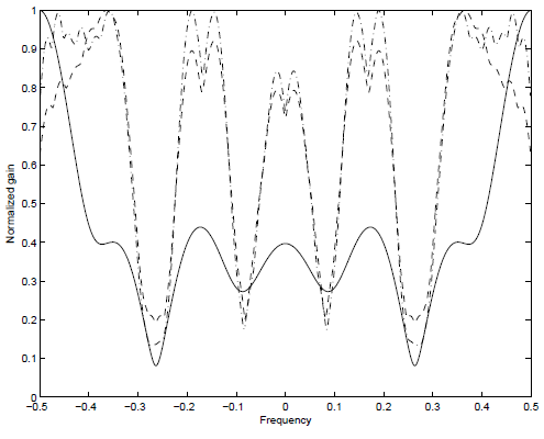
Figure 4: Average spectral magnitudes for transmit filters. SNR=10 dB, M = 16 and = 10−6. Legend: Dashed-dotted: Average spectral magnitudes for A1; Dotted: Average spectral magnitudes for A2; Solid: Channel transfer function magnitude |H(f)|.
VI. CONCLUSIONS
Assuming block transmissions for an ISI channel we have presented a structure of transceivers that operates with reduces redundancy. This structure consists of two different transceivers that act in an alternating way, i.e. one after the other. For further improvement of the spectral efficiency we have optimized the transmitters of both transceivers to achieve the maximum information rate. We have shown that the proposed scheme outperforms other approaches presented in the literature.
ACKNOWLEDGEMENTS
This work was funded by grants PIP-6344, FONCyT PAV-000127, and UBACyT I005
REFERENCES
1. Chow, J., J. Tu and J. Cioffi, "A discrete multitone transceiver system for HDSL applications," IEEE J. Select. Areas Communications, 9, 895-908 (1991).
2. Cioffi, J., G. P. Dudevoir, M. V. Eyuboglu and G. D. Froney, Jr., "MMSE decision-feedback equalizers and coding-Parts I and II," IEEE Trans. on Communications, 43, 2582-2604 (1995).
3. Cover, T.M and J. A. Thomas, Elements of Information Theory, New York, Wiley (1991).
4. Lechleider, J. W., "The optimum combination of block codes and receivers for arbitrary channels," IEEE Trans. on Commmunications, 38, 615-621 (1990).
5. Lin, Y. and S. Phoong, "Perfect discrete multitone modulation with optimal transceivers," IEEE Trans. on Signal Processing, 48, 1702-1711 (2000).
6. Lin, Y. and S. Phoong, "Optimal ISI-free DMT transceivers for distorted channels with colored noise," IEEE Trans. on Signal Processing, 49, 2702-2712 (2001).
7. Lin, Y. and S. Phoong, "Minimun redundacy for ISI free FIR filterbank tranceivers," IEEE Trans. on Signal Processing, 50, 842-853 (2002).
8. Scaglione, A., S. Barbarossa and G. B. Giannakis, "Filterbank transceivers optimizing information rate in block transmissions over dispersive channels," IEEE Trans. on Information Theory, 45, 1019-1032 (1999a).
9. Scaglione, A., G. B. Giannakis and S. Barbarossa, "Redundant filterbank precoders and equalizers-Parts I and II," IEEE Trans. on Signal Processing, 47, 1988-2022 (1999b).
Received: October 18, 2007.
Accepted: July 2, 2008.
Recommended by Guest Editors D. Alonso, J. Figueroa, E. Paolini and J. Solsona.
