


Servicios Personalizados
Articulo
 pdf en Inglés
 Articulo en XML
 Referencias del artículo
 Permalink
Latin American applied research
versión On-line ISSN 1851-8796
Lat. Am. appl. res. vol.43 no.3 Bahía Blanca jul. 2013
Carrier frequency offset compensation for ofdma systems using circular banded matrices
G.J. González, F.H. Gregorio and J.E. Cousseau
IIIE-CONICET, Department of Electrical and Computer Engineering Universidad Nacional del Sur, Av. Alem 1253,(8000) Bahía Blanca, ARGENTINA {ggonzalez, fernando.gregorio, jcousseau}@uns.edu.ar
Abstract — Orthogonal frequency division multiple access (OFDMA) is a multiuser communication technique that allocates to each user a set of orthogonal carriers. In the presence of carrier frequency offset (CFO) the orthogonality among carriers is lost and it is impossible to recover the information of the users without CFO compensation. The resulting multiple access interference (MAI) can be described as an interference matrix of large dimensions. In order to compensate for the CFO, this matrix must be inverted, what is computationally complex. Therefore, a banded matrix approximation is usually introduced. In this paper we propose a circular banded matrix which is a better approximation to the actual interference matrix. Also, by means of numerical simulation, we show that neither banded nor circular banded matrices approximations work well for normalized CFO close to 0.5.
Keywords — OFDMA; CFO Compensation; Banded Matrix.
I. INTRODUCTION
Orthogonal frequency division multiple access (OFDMA) is considered one of the most promising techniques to deliver high data rate in a multiuser wireless system. OFDMA is based on the inherited orthogonality of the orthogonal frequency-division multiplexing (OFDM) modulation. Then, a subset of subcarriers are assigned to each user according to a carrier allocation scheme (CAS).
The usual CASs are: subband, interleaved and generalized. In subband CAS, each user take a contiguous set of subcarriers. In interleaved CAS, the carriers of each user are uniformly distributed over the entire signal bandwidth to exploit the frequency diversity. Nevertheless, the more advantageous scheme is generalized CAS since it allows users to be allocated in the best subcarriers currently available for each one of them.
OFDMA provides high spectrum efficiency, robustness against multipath fading, simple equalization and low multiple access interference (MAI). On the other hand, as OFDM, OFDMA is highly sensitive to frequency synchronization errors. The carrier frequency offset (CFO) between the transmitter and the receiver destroys the orthogonality among carriers and, therefore, produces MAI. Downlink synchronization is a single parameter estimation problem and many algorithms proposed for OFDM can be used in that case (Schmidl and Cox, 1997; Ghogho et al., 2001; Morelli and Mengali, 1999). On the other hand, synchronization in the uplink is more challenging since it is a multiparameter estimation problem. The reason is that each user is characterized by particular CFO and channel parameters.
Frequency synchronization depends on the CAS and results in a two step procedure: 1) CFO estimation and 2) CFO compensation. Considering generalized CAS, CFO estimation employs a training sequence inserted at the beginning of the frame (Pun et al., 2007). On the other hand, CFO compensation uses iterative interference cancellation (Letaief and Huang, 2005; Sun and Zhang, 2009) or linear cancellation (Cao et al., 2007). Despite its larger computational complexity, the later compensation scheme is preferred since it leads to a better performance in bit error rate (BER) (Pun et al., 2007).
In Cao et al. (2007), the authors model the MAI as an interference matrix with the same dimension as the OFDMA system. Considering nowadays systems, this value could be as large as 2048 (IEEE, 2004). To compensate the CFO, the authors propose to use either the least squares (LS) or the minimum mean squared error (MMSE) criteria. Unfortunately, LS and MMSE requires the interference matrix inversion and a multiplication with the received symbol that results in a huge computational load. As a consequence, Cao et al. (2007) also proposes a banded system simplification to reduce the complexity of the linear cancellation. This simplification leaves some residual MAI which degrades the system performance. Additionally, as the nature of CFO interference is cyclic (depends on trigonometric functions), the actual interference matrix is circular banded. This means that the first and last carriers interfere with each other in case that the bandwidth of the banded matrix is less than the amount of virtual carriers of the system.
In this paper we propose a novel approximation of the interference matrix with cyclic banded structure that takes into account the interference at the edges and, of the OFDMA symbol if the virtual or null system carriers are not enough. As a consequence, it results in a better approximation than the banded matrix. Also, we derive low-complexity versions of the LU factorization, the forward and backward substitution for the inversion of the cyclic banded matrix. Additionally, we show by simulations that, as long as the CFO is close to 0.5, neither the banded nor the circular banded approximations are good, what makes frequency compensation impossible.
The paper is presented as follows: In Section 2 we describe the uplink OFDMA system and introduce the interference matrix. The CFO compensation criteria, the interference matrix structure and its approximations are introduced in Section 3. In Section 4 the numerical simulations are presented. Finally, Section 5 concludes the paper.
II. UPLINK SIGNAL DESCRIPTION
A.OFDMA signal
Consider an OFDMA symbol of N subcarriers, where M of them are used for data transmission (M<N) and the remaining are virtual carriers located at the edge of the band, i.e. Nvc =(N−M)/2, with (N−M) even. Virtual carriers (VC) avoid frequency leakage to the neighbor bands (IEEE, 2004). Useful subcarriers are divided in K subchannels of Nk = M/K carriers, each corresponding to a different user. In order to allow a tractable carrier assignment scheme, each subchannel is composed by an entire number of tiles of size Nt. Figure 1 illustrates an example of generalized CAS.
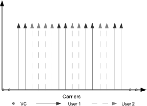
Generalized CAS with N=20, M=16, K=2 and Nt=2.
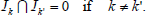
The subcarrier index of each user is defined as 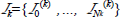 according to the CAS, where (.)(k) enotes assignment to user k. From the above definitions, the sets of carrier indexes are complete (contain the M carriers) and disjoint, then
 | (1) |
and
 | (2) |
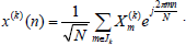
Each user transmits a frequency domain symbol defined as  , where
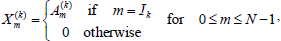 | (3) |
and Am(k) is the symbol sent by the user k at carrier m. By applying the inverse fast Fourier transform (IFFT) to Xm(k), we obtain the N time domain samples of the OFDMA symbol corresponding to user k
 | (4) |
A cyclic prefix (CP) of length Ncp is inserted at the beginning of the OFDMA symbol. The CP is assumed long enough to contemplate both the channel delay spread and the timing offset of each user. This is known as quasi-synchronous scenario and allow us to separate time and frequency estimation (Barbarossa et al., 2002).
At the base station, after discarding the CP, the received signal is the superposition of the signals of each user, and it can be described as
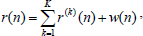 | (5) |
where
 | (6) |
w(n) is the AWGN, Hm(k) is the channel frequency response between the user k and the base station,  is the normalized CFO defined as
  , where
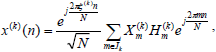
  is the CFO between the user k and the base station and ΔF is the intercarrier spacing. Then, the FFT is applied to the signal (5) to demodulate it. The output of the FFT block can be written as
 | (7) |
where
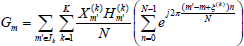 | (8) |
and Wm is the noise in each subcarrier.
B. Interference matrix
For the sake of clarity, lets express some of the previous equations in matrix form discarding VC. Define the received signal of a single OFDMA user as 
 . Considering that
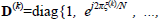
 is a diagonal matrix of
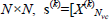
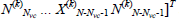 and F is the M×N FFT matrix with elements
 | (9) |
for 1≤ p≤ M and 1 ≤ q ≤ N, we can express (5) in matrix form as
 | (10) |
where
 | (11) |
and w is the AWGN vector. The ideal received signal in frequency, i.e. without CFO interference, is 
 where
where  Considering s(k), the signal of each user, we can write
 | (12) |
where  and
and
 | (13) |
Then, the signal after the OFDM demodulation results
 | (14) |
where
 | (15) |
and  Defining
  and considering (12), we have
 | (16) |
where
 | (17) |
The m-th row of the matrix Π describes the interference that each sent symbol produces on the m-th received carrier. As a consequence, Π can be interpreted as an interference matrix which relates the orthogonal frequency symbol s, with g the actual received symbol in the presence of CFO. For further details see Cao et al. (2007).
III. CFO COMPENSATION
In order to compensate the CFO effect we need to estimate s, denoted as s, from (14). Two estimation methods are proposed in Cao et al. (2004): least squares (LS) and minimum mean squared error (MMSE).
The LS is defined as
 | (18) |
when the right hand side expression is valid only if Π is full range. This compensation eliminates all interference caused by the CFO, at expense of increasing noise effects.
The solution based on the MMSE minimizes the overall effect of interference and noise. Lets define the autocorrelation matrix of s as  , the AWGN variance over each subcarrier as σn2 such that
 , where I is the M ×M identity matrix. E{.} denotes the expectation operator. The compensated symbol is defined as
 | |
 | (19) |
where in the second expression is considered that the average power over all subcarriers is σs2, and therefore 
The LS and MMSE compensations require the inversion of Π, as noted from (18) and (19). As stated in IEEE 802.16 (IEEE, 2004), N can be as large as 2048. This implies that the matrix inversion involves a significant computational complexity in real OFDMA systems. In the following sections we show that the structure of the interference matrix can be used to obtain an approximate solution of the CFO compensation.
A. Structure of the Interference Matrix
The interference of each user is described by the matrix Π(k) and depends on the CFO of this user. The elements of this matrix are (Pengfei and Zhang, 2009)
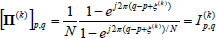 | (20) |
for 1≤p,q≤M. As noted from (17), the l-th column of Π is the l-th column of Π(k), where  Figure 2 illustrates an example of the structure of Π. Particularly, we emphasize the following aspects: 1) In the columns of Π, it can be noted the discontinuities due to the different CFO of each user, 2) the periodic structure of (20) makes Π a quasi-circulant matrix, and 3) the energy of the interference is concentrated for |q−p| close to 0 or N.
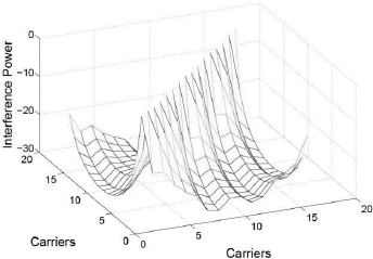
Figure 2: Interference matrix with N=16, K=2, Nt=2, ξ(1)=0.2 and ξ(2)= −0.3.
B. Banded and Circular Banded Approximations
In Cao et al. (2007), the authors propose an approximated interference matrix ΠB. This matrix with banded structure is defined as
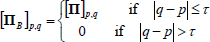 | (21) |
where τ is the matrix bandwidth. Due to the periodic structure of Π, τ≤2Nvc in order to discard the elements with the largest interference power. Banded matrix inverse requires much less computation compared with a complete matrix inverse (Golub and Van Loan, 1996). Efficient LU decomposition and forward/backward substitution algorithms for banded matrices are available in that case (Golub and Van Loan, 1996). As a consequence, this approximation allows a trade off between complexity and interference cancellation. In the following we refer this method as banded compensation (BC) However, if τ>2Nvc, there are some significant interference terms not considered in ΠB. In this work we propose an alternative matrix approximation with cyclic banded structure that takes into account the terms discarded by the banded approximation. The novel matrix is defined as
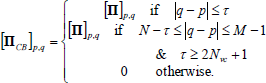 | (22) |
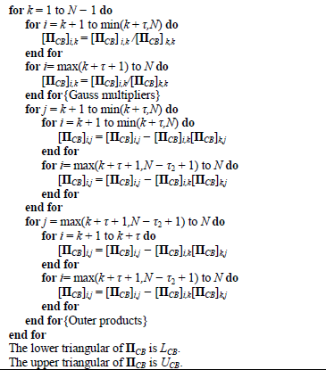
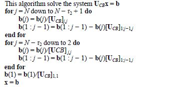
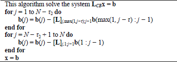
Roughly speaking, the circular matrix considers the replicated terms with the same interference power that those in BC, in case the VC do not mask them. In order to keep low compensation complexity, in Table 1 we propose a novel LU decomposition algorithm for ΠCB based on the algorithm for banded matrix proposed in Golub and Van Loan (1996). In the algorithms τ2=τ−2Nvc. This method is referred to as circular banded compensation (CBC). Similarly, we derive the backward and forward substitution algorithm for ΠCB which are shown in Tables 2 and 3.
Table 1: LU factorization for cyclic banded matrices
Table 2: Backward Substitution
Table 3: Forward Substitution
C. Computational Complexity
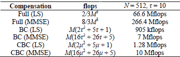
In this section we compare the computational complexity needed to compensate the CFO using the complete interference matrix, BC and CBC. In the Table 4 is the approximate number of flops (floating point operations) needed for each method, where μ = τ + τ2.
Table 4: Complexity comparison
Let consider ΠM as full, BC or CBC interference matrix. Then, the LS compensation can be broken down in: 1) LU factorization of ΠM, 2) forward substitution and, 3) backward substitution. On the other hand, the procedure to MMSE compensation is: 1) obtain 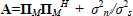 (note A is banded or circular banded with double bandwidth if ΠM is banded or circular banded), 2) LU factorization of A, 3) forward substitution, 4) backward substitution; and, 5) multiplication by matrix ΠMH.
IV. SIMULATIONS AND DISCUSSION
In this section we make performance comparisons between full, BC and CBC considering different τ and Nvc, for LS and MMSE criteria.
We chose an OFDMA symbol with N=128, Ncp=16, Nt=4, K=4 and Q-PSK for the modulation of the carriers. The GCAS is used to distribute the users among subcarriers. The static propagation channel  has length L=6, and exponential decay profile
  , where G is chosen such that
  and β|= 5. The results are averaged over 200 user allocations and 200 noise realization. For each assignment the CFO of each user is chosen randomly from the interval
In Fig. 3 we show the overall (considering all subcarriers) uncoded bit error rate (BER) versus SNR for the OFDMA system. The modulated symbols are equalized using LS as  for m∈k, where
  are the equalized symbols,
  the compensated symbols (using either LS or MMSE) and
  is the channel frequency response. In this case M = 128, i.e. there is no VC. As τ increases, CBC outperforms BC since more significant interference terms are considered.
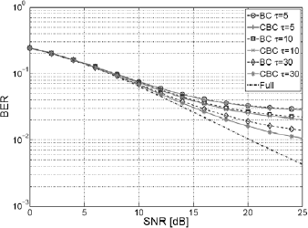
Figure 3: Bit error rate vs SNR for the LS method.
The same is shown for MMSE criterion in Fig. 4. As can be noted, there is not a notable improvement in the performance for this SNR range.
Figure 4: Bit error rate vs SNR for the MMSE method.
From the structure of the interference, shown in Fig. 2, it can be noted that for BC the subcarriers at the edge of the band are affected by a significant interference when  In Fig. 5 is illustrated the mean squared error (MSE) for each subcarrier after BC and CBC compensation. In this case is used GCAS, N = 64, M = 56, Nt = 4, K = 2 and τ = 15. The CFO is restricted to
  and
and  The simulation outcomes are averaged over 5000 realizations. From the figure, it is noted how CBC attains a better performance at the edges of the band.
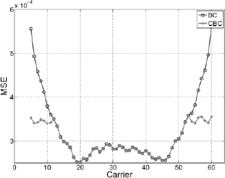
Figure 5: Mean squared error vs Carrier index.
In Cao et al. (2007) is reported the interference matrix Π is singular if
 | (23) |
where l and m are different users and Z is a nonzero integer. As a consequence, Π gets ill conditioned as  Although ΠB and ΠCB are well conditioned in the above situation, they do not provide a good approximation to the actual problem. Figure 6 shows the MSE for each carrier considering BC and CBC with LS criterion, for
  The high MSE in some carriers points out that the interference matrix is close to be singular in some realization.
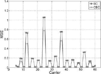
Figure 6: Mean squared error vs Carrier index. Π ill conditioned.
A direct consequence of the singularity of Π is that is not possible to use the interference matrix to compensate high CFO values since it is not possible to warranty that the condition (23) does not occur. At the beginning of the transmission, each receiver estimate its CFO and compensate it. Therefore, in the uplink the CFO is only due to the Doppler effect produced by the mobility of the user and the oscillator accuracy (Pun et al., 2007). In other words, the mobility and the quality of the oscillator must be considered in the system design to assure (23) does not occur.
As can be noted from Figs. 3 and 4, the performance of MAI cancellation for low SNR is poor. The same behavior also is noted in filter bank multicarrier (FBMC) techniques (Saeedi-Sourck et al., 2011), which is a more complex modulation system. The low side-lobe filters used in FBMC does not produce MAI even with few guard carriers, but the performance for an SNR of 10dB or lower is similar to OFDMA. The improvement of BER levels employing channel coding is a current topic of research.
V. CONCLUSION
In this work we study the problem of CFO compensation in the uplink of an OFDMA system. We introduce a novel approximation of the interference matrix with circular banded structure and propose low-complexity algorithms to operate with this matrix.
In simulations, our approximation outperforms the banded approximation proposed in a recent work when virtual carriers are not enough to cover the significant interference term. The overall bit error rate and the mean squared error of the subcarriers at the edges of the OFDMA symbol are improved. If virtual carriers mask the major interference, our proposal reduces to the banded approximation.
Neither the circular banded nor the banded compensation are useful when the CFO of the users is close to half the normalized intercarrier spacing. Another compensation technique is required in case the OFDMA system could not be designed to assure a CFO in this operation range.
REFERENCES
1. Barbarossa, S., M. Pompili and G.B. Giannakis, "Channel-independent synchronization of orthogonal frequency division multiple access systems," IEEE J. Sel. Areas Commun., 20, 474-486 (2002).
2. Cao, Z., U. Tureli and Y.-D. Yao, "Frequency synchronization for generalized OFDMA uplink," IEEE Global Telecommunications Conference, 2, 1071-1075 (2004).
3. Cao, Z., U. Tureli and Y.-D. Yao, "Low-complexity orthogonal spectral signal construction for generalized OFDMA uplink with frequency synchronization errors," IEEE Trans. Veh. Technol., 56, 1143-1154 (2007).
4. IEEE, IEEE standard for local and metropolitan area networks part 16: Air interface for fixed broadband wireless access systems, IEEE Std 802.16-2004. Revision of IEEE Std 802.16-2001 (2004).
5. Letaief, K.B. and D. Huang, "An interference-cancellation scheme for carrier-frequency offsets correction in OFDMA systems," IEEE Trans. Commun., 53, 203-204 (2005).
6. Ghogho, M., A. Swami and G. Giannakis, "Optimized nullsubcarrier selection for CFO estimation in OFDM over frequency-selective fading channels," Proc. IEEE GLOBECOM, 202-206 (2001).
7. Golub, G.H. and C.F. Van Loan, Matrix Computations, The Johns Hopkins Univ. Press, 3rd ed. (1996).
8. Morelli, M. and U. Mengali, "An improved frequency offset estimator for OFDM applications," IEEE Commun. Lett., 3, 75 -77 (1999).
9. Pun, M-O., M. Morelli and C. C. Jay Kuo, Multi-Carrier Techniques For Broadband Wireless Communications: A Signal Processing Perspectives. Imperial College Press, London, UK (2007).
10. Saeedi-Sourck, H., Y. Wu, J.W.M. Bergmans, S. Sadri, and B. Farhang-Boroujeny, "Complexity and performance comparison of filter bank multicarrier and OFDM in uplink of multicarrier multiple access networks," IEEE Trans. Signal Process., 59, 1907 -1912 (2011).
11. Schmidl, T.M. and D.C. Cox, "Robust frequency and timing synchronization for OFDM," IEEE Trans. Commun., 45, 1613-1621 (1997).
12. Sun, P. and Li Zhang, "Low complexity iterative interference cancelation for OFDMA uplink with carrier frequency offsets," 15th Asia-Pacific Conference on Communications, 390-393 (2009).
Received: June 11, 2012
Accepted: October 10, 2012
Recommended by Subject Editor: Gastón Schlotthauer and María Eugenia Torres
