


Servicios Personalizados
Articulo
 pdf en Inglés
 Articulo en XML
 Referencias del artículo
 Permalink
Latin American applied research
versión On-line ISSN 1851-8796
Lat. Am. appl. res. vol.43 no.4 Bahía Blanca oct. 2013
Numerical study of heat transfer by convection and thermal radiation in a ventilated room with human heat generation and co2 production
N.A. Rodriguez Muñoz, Z.C. Briceño Ahumada and J.F. Hinojosa Palafox
Departamento de Ing. Química y Metalurgia, Universidad de Sonora, 83000 Hermosillo, SON, MEXICO. fhinojosa@iq.uson.mx
Abstract— The purpose of this work is to study the combined effect of heat generation produced by a human being and the mixed turbulent convection with thermal radiation, as well as the CO2 production from respiration. These factors are important to achieve healthy and pleasant indoor comfort conditions and to optimize the energy use in buildings. Numerical results in a rectangular ventilated room (3.0 m x 2.5 m) were carried out considering temperatures on the vertical walls of 298 and 308 K (25 and 35 °C) and the remaining walls were considered as adiabatic. The temperature surface of the human being was maintained at 307 K (34 °C). The inlet velocities were 0.05 m/s and 0.5 m/s, whereas the assumed emissivity values of the walls were 0.0 and 0.8. The mathematical model was solved numerically with software of Computational Fluid Dynamics. The flow patterns (streamlines), the temperature fields (isotherms) and CO2 concentration distributions are presented and discussed. Besides the heat transfer coefficients are reported. The results show that the natural ventilation reduces the average temperatures in the room between 4°C and 5.5°C, while the thermal radiation increases the average temperature between 0.2°C and 0.4°C.
Keywords— CO2 Production; Mixed Convection; Thermal Radiation; Ventilated; Cavity; CFD.
I. INTRODUCTION
Growth in population, enhancement of building services and comfort levels, together with the rise in time spent inside buildings, have raised building energy consumption to the levels of transport and industry. For example, the members of the Organization for Economic Co-operation and Development (OECD) consume between 15 and 25% of their primary energy in this sector and the developing countries a higher amount (Dzioubinski and Chipman, 1999). The emphasis on reducing energy consumption and the environmental consciousness have motivated researchers and designers to consider the potential of natural ventilation, as a result new ventilation standards and guidelines have been written to reflect the importance of ventilation on the quality of indoor environment (Awbi, 2003).
The air quality problems have been associated with high concentrations of internally generated pollutants, like CO2, and low outdoor air supply rates (Robertson, et al., 1985), on the other hand forced and natural ventilations are two possible mechanisms of ventilation, unlike forced ventilation, natural ventilation takes place by the wind and buoyancy effects, and it is an energy-saving approach (Rahimi and Arianmehr, 2011).
However the prediction of air movement and thermal parameters in ventilated rooms is complex, because of the coupling of the heat transfer mechanisms inside the habitation. A good way to analyze air movement in ventilated rooms is through numerical studies using computational fluid dynamics (CFD), because the modeling allows the prediction of the variables behavior inside the system. In the literature several numerical studies of air movement and heat transfer in ventilated cavities are reported, which can be categorized as (a) air movement and heat transfer in a ventilated cavities without contaminants and (b) air movement and heat transfer in a ventilated cavities with contaminants. Next the studies of air movement in ventilated cavities are briefly described.
(a) Air movement and heat transfer in ventilated room without contaminants.
Costa et al. (2000) studied a two-dimensional cavity to discuss the influences of the aspect ratio of the room, the air inlets, the wall temperatures, the heating/ventilation ratio and the maximum speed of the return flow. The authors emphasize that there is evidence that the ventilation requirements in non-industrial buildings involve flows in mixed convection regimen, where greater changes in flow patterns occur. Raji and Hasnaoui (2000) presented results of heat transfer by mixed convection in a two-dimensional rectangular cavity with heat fluxes on a vertical wall and on the top wall, the authors also considered the radiative effect on the streamlines and isotherms. Results show that the configuration with inlet at the bottom and the outlet at the top is more useful to reduce the mean temperatures inside the cavity for Re£1000.
Singh and Sharif, (2003) performed a numerical study about the mixed convection in two-dimensional cavities with differentially heated walls, the authors aimed to optimize the air inlet and outlet positions to identify the most effective way to remove heat from the cavity. Moraga and Lopez, (2004) presented a numerical analysis of the fluid mechanics and heat transfer for three-dimensional mixed convection in an air-cooled cavity. The air inlet is through a rectangular opening, with a cross section of L x L=15 and located at the top of the left vertical isothermal wall. Calculations were performed for air, Reynolds numbers in the range 1≤Re≤500 and Richardson numbers between 0≤Ri≤18. The comparison between 3-D and 2-D simulations showed that a 3-D model is needed to capture the fluid mechanics for Ri=10 when 10≤Re≤250 and to calculate the global Nusselt number when Re =500 for Ri<1.
Rahman et al. (2007) performed a numerical study on mixed convection in a two-dimensional vented enclosure. Various inlet port configurations are extensively studied with the change of governing parameters. The streamlines, isotherms, average temperature and average Nusselt number of the heated wall were presented for Ri=0 to 10, Re=50, 100 and 200; Pr = 0.71, 7.5 and 50 and different inlet position heights: Hi=0.05, 0.50 and 0.95. It is found that with the increase of Reynolds and Richardson numbers the convective heat transfer becomes predominant over the conduction and the rate of heat transfer from the heated wall significantly depends of inlet port position. Saha et al. (2008) studied numerically the behavior of mixed convection in a two-dimensional rectangular cavity with constant heat flux on a vertical surface, trying out four different inlet and outlet positions in the cavity and obtaining results for a Richardson number from 0 to 10 and Reynolds number of 100. The results show that the mean Nusselt number and the non-dimensional temperature of the heat source surface depend solely of the inlet and outlet position.
(b) Air movement and heat transfer in ventilated room with contaminants.
Soria et al. (1998) reported the results of a numerical study on the transient removal of a contaminant from a two-dimensional enclosure with one inlet and one outlet. The influence of buoyancy forces due to thermal and concentration gradients, contaminant diffusivity, inlet velocity and outlet disposition over the cleaning-time are studied. For isothermal situations, the time required to remove the contaminant is studied parametrically as a function of the outlet position and the governing dimensionless numbers (Reynolds number, Schmidt number and Rayleigh number). Buoyancy forces are found to have a strong influence over the flows and in consequence over the cleaning times. Hyun and Kleinstreuer, (2001) studied the effect of transient breathing on trace gas ambient concentrations and ultimately the uptake by the subject for three different orientations with respect to the non-isothermal air stream and the location of the tracer gas source. The authors experimentally validated CFD simulations of transient turbulent non-isothermal flow with tracer gas transport in a personal exposure environment. Tian et al. (2006) investigated three turbulence models: standard k-ε, re-normalization group (RNG) k-ε and RNG-based large eddy simulation (LES) model, to simulate indoor contaminant particle dispersion and concentration distribution in a model room. The flow of contaminant particles (with diameters of 1 and 10 mm) is simulated within the indoor airflow environment of the model room. The RNG-based LES model has shown to yield the best agreement.
Liu et al. (2008) reported the results of a numerical study on removal of two contaminants from a three-dimensional enclosure with one inlet, one exhausting port and one returning port. The influence of inlet velocity, fresh air ratio, recirculating air filtered removal efficiency and contaminant property is investigated. The results show that the Reynolds and Schmidt number have complex influence to indoor contaminant removal. Salinas et al. (2008) carried out a study that shows the relationship of the transport of heat and mass (double) in a rectangular cavity caused by a forced and natural convection. The parameters studied were: 10 ≤Re≤150, N=2.5, Pr=7.0, GrT=104, Le=100, A=2. The results show that the conjugated phenomena is only visible (flow alteration) for mixed flows with a low Reynolds number. Xamán et al. (2009) obtained results from the analysis of the heat and mass transfer of an air-carbon dioxide mixture (CO2) inside a two-dimensional ventilated cavity in laminar flow regime. Different configurations of the cavity were analyzed regarding the location of the mixture outlet gap, and three different values for the CO2 contaminant source (1000, 2000, 3000 ppm) were studied. The inlet air velocity is a function of the Reynolds number (10 ≤Re≤ 500). Based on the results, from a thermal comfort point of view and air quality, configuration D (outlet on right of the top wall of the cavity) shows the best performance in the interval 10≤Re≤100, with an exception for the case when a contaminant source of 1000 ppm is present where configuration C (outlet at the middle of the top wall) is recommended.
The literature review indicates that there are no reported numerical studies considering the combined effect of heat generation produced by a human being, mixed convection and the CO2 production from respiration in naturally ventilated cavities with turbulent flow. Considering the above, this paper presents a numerical analysis of the interaction between the heat transfer mechanisms (convection and thermal radiation) and CO2 distribution in a ventilated two-dimensional cavity with a heat source. The numerical results were obtained considering two velocities of air inlet (0.05 and 0.5 m/s). The study was performed considering a turbulent flow regimen. The flow patterns (streamlines), the temperature fields (isotherms) and CO2 concentration distributions are presented and discussed. Besides the heat transfer coefficients are reported.
II. PHYSICAL PROBLEM AND MATHEMATICAL MODEL
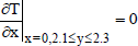
The study of the air movement and heat transfer in a ventilated cavity (3.0 m x 2.5 m) with a heat source (human being) and CO2 production, was carried out as shown in Fig. 1. It was considered the natural and forced convection coupled with the thermal radiation exchange among the walls and heat source. The left and right vertical walls were assumed isothermal, whereas the remaining walls were considered as adiabatic and diffuse emitters. The heat source was maintained at 34°C by considering the mean skin temperature of nude body at an ambient temperature of 30°C (Awbi, 2003). The thermal fluid is air and it is not involved in radiative heat transfer. The fluid flow is assumed as turbulent. The coordinates of the outlet and inlet positions are (0,2.1≤y≤2.3) and (3.0,0.2≤y≤0.4), respectively. Two different wall emissivity values were considered: 0.0 and 0.8, the air. The e=0.8 value was chosen, since it corresponds to a painted surface. Because the recommended outdoor air supply rates are 8 to 10 l/s for inside office spaces, office conference rooms and classrooms, thereby an exceeded air velocity inlet was chosen (0.5 m/s) to reach an adequate ventilation rate required for a given room to satisfy both health and comfort criteria (ASHRAE Standard 62, 1999). The air inlet temperature was considered as Tin=25°C. However the CO2 production of an average sedentary adult is about 0.005 l/s (18 l/h) and the expired air contains about 4% by volume of CO2. Besides, the maximum CO2 concentration allowed for 8 h occupation is 0.5% (Awbi, 2003), although it has been reported that concentrations below 0.1 % are required to avoid discomfort and headache (Sundell, 1982). The above criteria were taken into consideration to specify the boundary condition of the human respiration.
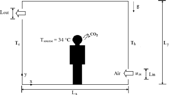
Figure 1 Physical model of the ventilated cavity.
The governing equations (mass conservation, momentum, energy and species), in time averaged tensor notation, for the steady state with the Boussinesq approximation are as follow:
Continuity:
 | (1) |
Momentum:
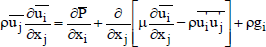 | (2) |
Energy:
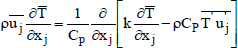 | (3) |
Species:
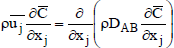 | (4) |
where xi and xj are the Cartesian coordinates of the system (i=x,y and j=x,y),  is the mean velocity,
  is the mean dynamic pressure,
  is the mean temperature, g is the gravitational acceleration. μ, ρ, β, Cp, DAB, are the dynamic viscosity, density, the coefficient of thermal expansion, the specific heat at constant pressure and mass diffusivity, respectively.
The above set of equations is not complete, due to the presence of the Reynolds stress tensor (  ) in the momentum equation and the turbulent heat flux vector (
  ) in the energy equation. In the family of eddy viscosity models (EVM), the Reynolds stress tensor is established through the Boussinesq hypothesis as:
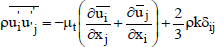 | (5) |
The model of high Reynolds number (HRN) considers that the turbulent viscosity (μt) is given by:
 | (6) |
where Cμ is a constant. The turbulent heat fluxes are expressed as:
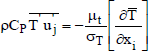 | (7) |
where σT is the turbulent Prandtl number.
The turbulent kinetic energy (kt) and the dissipation of the turbulent kinetic energy (εt) are obtained from their transport equations by using the kt-εt model (Ince and Launder, 1989):
Turbulent kinetic energy (kt):
 | (8) |
Dissipation of the turbulent kinetic energy (εt):
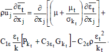 | (9) |
In above equations, Pkt represents the generation of the turbulent kinetic energy caused by velocity gradients and Gkt is the generation of turbulent kinetic energy due to the buoyancy force. The terms C1ε and C2ε are coefficients; whereas σk and σε are the turbulent Prandtl numbers for the equations of kt and εt respectively. In mathematical form:
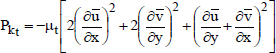 | (10) |
 | (11) |
The radiative energy transfer in a non-isotropic medium which absorb, emits and scatters radiation, is described mathematically by the radiative transfer equation (RTE):
 | (12) |
where Iη is the intensity of radiation, s is the geometric path length, ŝi is the unit vector in a given direction, Ibη is the blackbody intensity, ŝ is the propagation direction, kη is the absorptivity, βη is the coefficient of extinction, σsη is the scattering coefficient and Ωi is the solid angle. However because it is considered the air as non-participating media, the Eq. (12) becomes:
 | (13) |
The Eq. (13) indicates that the intensity of radiation is constant along a given path length and that the radiation heat transfer occurs through radiative exchange among the walls and the heat source of the cavity.
At an opaque surface, the leaving intensity (also called radiosity) is composed of the emitted intensity and the reflected irradiation and is given by:
 | (14) |
where ε and ρ are the emissivity and reflectivity respectively.
The net radiant heat flux of a surface is the difference between the radiosity and irradiation:
 | (15) |
The hydrodynamic boundary conditions were obtained by assuming non-slip condition on the walls, therefore the velocity components are equal to zero. Because the air was considered to enter perpendicularly to the opening, the x-component of the velocity had a constant value whereas the remaining components are equal to zero. For the outlets a fully developed flow was assumed, therefore the diffusive transport is negligible. The turbulent kinetic energy and the dissipation of the turbulent kinetic energy for the incoming air were obtained by applying the empirical correlations (Nielsen, 1990):
 | (16) |
 | (17) |
The thermal boundary conditions used in this study are as follows:
 | (18) |
 | (19) |
 | (20) |
 | (21) |
 | (22) |
 | (23) |
where qr1 and qr2 are the net radiative heat fluxes of the corresponding adiabatic surface.
The boundary conditions for CO2 are:
 | (24) |
 | (25) |
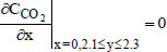 | (26) |
To generalize the results, the non-dimensional Reynolds (Re) and Rayleigh (Ra) numbers, were defined as follows:
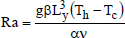 | (27) |
 | (28) |
where g is the gravity, Ly is the height of the cavity, Uin is the inlet velocity, α and ν are the thermal diffusivity and the kinematic viscosity of the fluid respectively. The non-dimensional heat transfer parameters are explained next.
The local convective Nusselt number is defined as the ratio between the heat flux by natural convection and the heat flux due to conduction only:
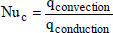 | (29) |
The average convective Nusselt number was obtained by integrating the local Nusselt number over the area of an isothermal wall:
 | (30) |
where  is the average convective heat transfer coefficient and λ is the thermal conductivity of the fluid.
The radiative Nusselt number is defined as the ratio between the radiative heat flux and the heat flux due to conduction only, then:
 | (31) |
The average radiative Nusselt ( r) number was obtained integrating the radiative Nusselt numbers over the isothermal wall, by the following mathematical relationship:
 | (32) |
The total average Nusselt number (t) was calculated by summing the average convective Nusselt number and the average radiative Nusselt number.
III. NUMERICAL METHOD OF SOLUTION
The numerical results were obtained using the CFD software Fluent 6.3, which is based on the finite volume method in order to solve the governing equations of the fluid dynamics. For the coupling of the momentum and continuity equations the SIMPLEC algorithm were used. The convective terms were discretized applying the Power Law scheme (Patankar, 1980). The convergence was achieved when the weighted residue of each
of the governing equations was 10-3. The radiative heat transfer Eqs. (12-14) were solved with the discrete ordinate method, which subdivides the solution domain into a number of control volumes. Also the directions of propagation of the radiative intensity are discretized and the integrals taking into account the scattering are approximated as appropriately weighted sums. For example the radiative transfer equation at a discrete direction for one-dimensional problems can be written as
 | (33) |
where  are the quadrature weights (there is no solid angle integration). However quadrature sets (ordinate directions and angular weights) are generated to integrate the radiant energy and scattering terms accurately (Sanchez and Smith, 1992).
To determinate the appropriate mesh size for the parametric study on the two-dimensional cavity; a mesh independence study was carried out considering a velocity inlet of 0.5 m/s. A non-uniform mesh with greater node density on the heated and isothermal wall was placed. The averaged Nusselt number value on the cold isothermal wall was independent of the mesh size when 150 nodes on the horizontal direction and 150 nodes on the vertical direction were used (29 260 cells).
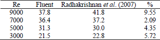
In order to validate the numerical code, a comparison between experimental results from a ventilated cavity of Radhakrishnan et al. (2007) was carried out. The results were compared with the ones obtained with Fluent, with a mesh size of 50900 nodes and the turbulent kt-εt standard model. The heat power of the source was kept at 10.1 W and the Reynolds numbers was varied between 3000 and 9000. In Table 1, the Nusselt number percentage differences are calculated, showing that the maximum absolute difference was 9.55 % for a Re=9000, meanwhile the minimum difference was 2.09 for Re=7000.
Table 1 Nusselt number comparison between Radhakrishnan et al. (2007) and Fluent.
IV. RESULTS
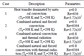
The numerical results for the ventilated cavity were obtained considering the parameters of Table 2. The incoming air velocities considered (0.05 and 0.5 m/s) are equivalent to Reynolds numbers of 636 and 6364, whereas the Rayleigh number was fixed at 3.72x10⁷.
Table 2 Considered cases for parametric study.
Case 1. Heat transfer dominated by natural convection.
In order to analyze the influence of natural convection on the flow pattern, temperature field and CO2 distribution, the thermal radiation was suppressed by setting an emissivity value of zero and the forced convection was considerably reduced by considering a low Reynolds number (Re=636). On Fig. 2 the results of heat transfer dominated by natural convection are shown. The streamlines on Fig. 2a indicate that the flow of the fluid occurs in counterclockwise direction, with velocity magnitudes between 0.05 m/s and 0.15 m/s. The hot wall heats the fluid, then the air raises driven by the buoyancy force and descends near the cold wall moving towards the human, rising again and continuing to go upwards to the outlet. In the upper right corner a counter clockwise vortex is observed, however on the right side of the human a vortex moving in clockwise direction can be noted. In the temperature field can be observed (Fig. 2b) that low temperature predominance exists on the lower part of the left side of the room (≈28°C) and higher temperatures (between 30-33°C) can be observed near the top and the right side of the room. The mean temperature of the room was 31.4°C. The CO2 concentration field in volume percentage is shown in Fig. 2c, where can be observed that the concentration of CO2 is about 1.0 % in the room, except near the CO2 outlet (human) where it is 2.4 % and near the air inlet where is between 0.0-0.5%. The mean volume percentage of CO2 in the room is 0.57%.
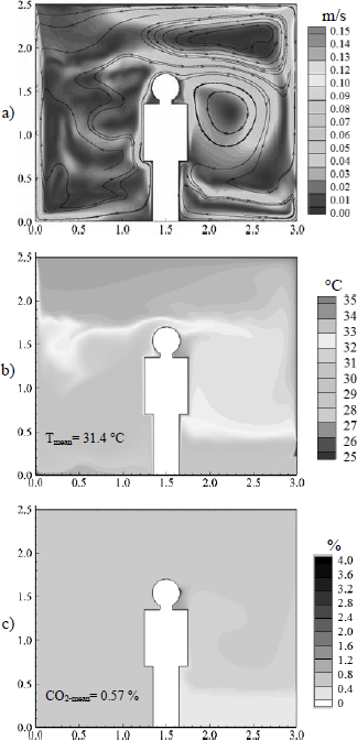
Figure 2 Heat transfer dominated by natural convection: a) Flow pattern (streamlines and velocity magnitude), b) Temperature field (isotherms) and c) CO2 distribution (% volume).
Case 2. Combined natural and forced convection.
Figure 3 presents the results for combined natural and forced convection. In Fig. 3a velocity magnitudes between 0.05 m/s and 0.5 m/s are observed, besides a big vortex on the left side and three medium vortexes on the right side of the room are formed. The direction on the vortexes is influenced by the incoming air, except the one on the upper right corner, which is influenced by the nearby hot wall and it circulates in counterclockwise direction. In the temperature field can be observed (Fig. 3b) that the low temperature area is influenced by the air that enters the room, and the hot temperature area is located near the cold wall, where almost no influence of the incoming cold air can be noticed. Thermal stratification cannot be observed for this case, only a small influence of natural convection in the upper right side of the room, near the hot wall. The Tmean in the room for Case 2 is 26.8°C. In Figure 3c, the CO2 concentration (%) field is shown, for this case most of the room has 0 % of CO2, except near the CO2 human outlet and the mean CO2 percentage in the room is 0.01%.
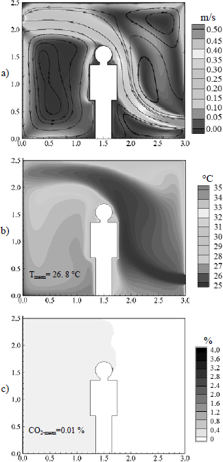
Figure 3 Combined natural and forced convection: a) Flow pattern (streamlines and velocity magnitude), b) Temperature field (isotherms) and c) CO2 distribution (% volume).
Case 3. Combined natural convection and thermal radiation.
On the Fig. 4 the results for natural convection with radiation are shown. On the Figure (4a) the flow pattern is alike to the observed for Case 1, nevertheless a bigger vortex located on the superior part of the room is appreciated. In Figure 4b, also a similar behavior as the Case 1 (almost pure natural convection) is observed, the lower temperature values are located on the lower left part of the room and higher temperatures can be observed near the hot wall as well as near the human. However the thermal radiation causes that the overall temperatures on the room become lower than the ones for Case 1. Furthermore Tmean=31.4 °C for Case 1, meanwhile Tmean=31 °C for Case 3. In the CO2 concentration field shown in Figure 4c can be observed that the CO2 distribution on the room is almost homogeneous. Only around the CO2 outlet (human) is where higher concentrations can be observed, the lower concentrations are close to the air inlet, whereas the mean CO2 percentage in the room is 0.80%.
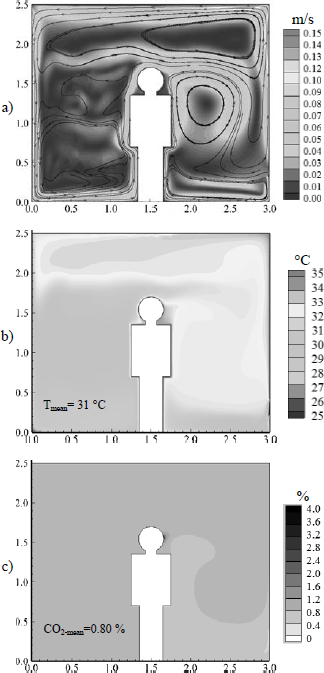
Figure 4 Combined natural convection and thermal radiation: a) Flow pattern (streamlines and velocity magnitude), b) Temperature field (isotherms) and c) CO2 distribution (% volume).
Case 4. Combined natural and forced convection and thermal radiation.
Figure 5 shows the results for combined natural convection and forced convection with thermal radiation. In the streamlines (Fig. 5a) three vortexes appear on the right side of the room, two of them rotate in the clockwise direction because the incoming air flow, but the vortex on the upper right corner is moving in opposite direction, due to the buoyancy force caused by the closeness to the hot wall. However on the left side a big vortex near the cold wall appears with counterclockwise direction. The flow patterns in the cases where forced convection is considered (3 and 5) are comparable, because it dominates the air movement. In this case the velocity magnitudes are within 0.05 m/s and 0.15 m/s. However the temperature field observed in Figure 5b, shows a similar behavior as the case considering natural and forced convection (Case 2), nevertheless, with the incorporation of the radiative effect, a minor rise of temperatures on the room is caused (0.2°C). Nevertheless, the temperature field pattern is alike. In Figure 5c, the CO2 concentration (% volume) field is shown, for this case most of the room has a 0.0 % of CO2, except near the CO2 outlet (human), the mean CO2 percentage in the room is 0.01%. This behavior is noted for all cases including forced convection (Cases: 3 and 5).
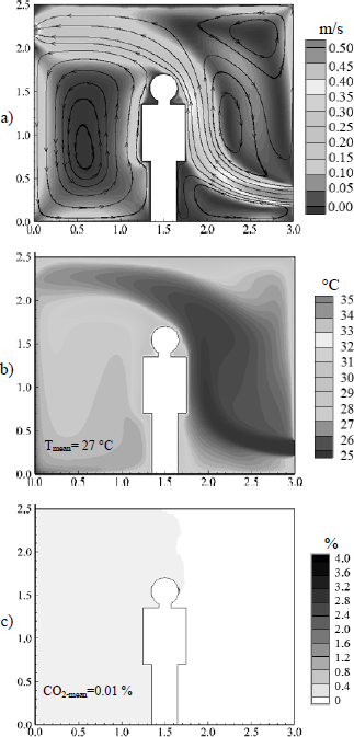
Figure 5 Combined natural and forced convection with thermal radiation: a) Flow pattern (streamlines and velocity magnitude), b) Temperature field (isotherms) and c) CO2 distribution (% volume).
Heat transfer analysis.
In Table 3 are presented the average Nusselt numbers on cold isothermal wall (convective, radiative and total). It can be observed that the Nusselt numbers decrease with the Reynolds number. Besides the higher average convective Nusselt numbers are observed when natural convection without forced convection is considered. When thermal radiation is present (Cases 3 and 4), can be noted that the lowest percentage contribution of the radiative heat transfer is for Case 3 (57%) and the highest for Case 4 (73%). However an increase of 137 % on the total Nusselt number ( ) between Case 1 (almost pure natural convection) and Case 3 (almost pure natural convection and thermal radiation) is observed. Meanwhile the total Nusselt numbers grows 333 % when Case 2 (natural and forced convection) is compared with Case 4 (natural and forced convection with thermal radiation).
Table 3 Average Nusselt numbers.

V. CONCLUSIONS
In this work the numerical study of heat transfer by convection and thermal radiation in a ventilated room with human heat generation and CO2 production is presented. From the results we can conclude the following:
- The flow pattern is strongly influenced by forced convection, whereas the presence of thermal radiation slightly varies the flow pattern.
- The temperature pattern is greatly influenced by the consideration of forced convection, nevertheless, near the hot wall; the influence of natural convection is always noticeable. Furthermore the natural ventilation reduces the average temperatures in the room between 4°C and 5.5°C, while the thermal radiation increases the average temperature between 0.2°C and 0.4°C.
- The CO2 concentration in percentage is only influenced by the forced convection inclusion, noting that it causes 98% of decrease on the % of CO2.
- The higher average convective Nusselt numbers are observed when natural convection without forced convection is considered. Besides the inclusion of the thermal radiation causes an increase on the total Nusselt number () of 137 % (when almost pure natural convection is considered) and 333% (when natural and forced convection are considered).
NOMENCLATURE
| CCO2-in | Concentration of CO2 at inlet, mole/l |
 | Averaged concentration of species, mole/l |
| Cp | Specific heat, J/kgxK |
| C1 | Turbulent model coefficients |
| C2e | Turbulent model coefficients |
| DAB | Mass diffusivity, m2 s |
| g | Gravity, m/s2 |
| Gkt | Generation of turbulent kinetic energy due to the buoyancy force, m2/s3 |
 | Average heat transfer coefficient, W/m2xK |
 | Blackbody intensity, W/m2 |
 | Intensity of radiation, W/m2 |
| Kt | Turbulent kinetic energy, m2/s2 |
| Kin | Inlet turbulent kinetic energy, m2/s2 |
| Kη | Absorptivity, non-dimensional |
| Lx | Length of the cavity, m |
| Ly | Height of the cavity, m |
| Lin | Inlet height, m |
| Nu | Local Nusselt number, non-dimensional |
 | Average convective Nusselt number,  |
| Average Radiative Nusselt number, 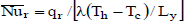 , non-dimensional , non-dimensional |
 | Average total Nusselt number  , non-dimensional , non-dimensional |
| Pr | Prandtl Number, non-dimensional |
| Pkt | Generation of the turbulent kinetic energy by velocity gradients, m2/s3 |
| Ra | Rayleigh number, 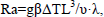 non-dimensional non-dimensional |
| Re | Reynolds number,  non-dimensional non-dimensional |
| s | Geometric path lenght, m |
 | Unit vector in a given direction, m |
 | Propagation direction, m |
| Tc | Cold wall temperature, K |
| Th | Hot wall temperature, K |
| Tin | Inlet temperature, K |
| Tmean | Average temperature, K |
| ui' | Instant velocity fluctuation on i direction, m/s |
| Uin' | Inlet velocity, m/s |
| ūi' | Time averaged velocity on i direction, m/s |
| Greek symbols | |
| α | Thermal diffusivity, m/s |
| β | Coefficient of thermal expansion, 1/K |
| βπ | Coefficient of extinction, 1/m |
| ε | Emissitivity, non-dimensional |
| εt | Turbulent kinetic energy dissipation, m2/s3 |
| εin | Inlet turbulent kinetic energy dissipation, m2/s3 |
| µ | Dynamic viscosity, kg/m·s |
| µt | Turbulent viscosity, kg/m·s |
| ρ | Density, kg/m3 |
| Ωi | Solid angle, sr |
| σk | Turbulent Prandtl numbers for the equation of kt, non-dimensional |
| σs | Turbulent Prandtl numbers for the equation of εt, non-dimensional |
| σsn | Scattering coefficient, 1/m |
| υsn | Kinematic viscosity, m2/s |
REFERENCES
1. ASHRAE Standard 62, Ventilation for Acceptable Indoor Air Quality, American Society of Heating, Refrigeration and Air-Conditioning Engineers, Atlanta, GA (1999).
2. Awbi, H. Ventilation of Buildings. E & FN Spon, 2, 80 (2003).
3. Costa, J.J., L.A. Oliveira and D. Blay, "Turbulent airflow in a Room with Two-Jet Heating-Ventilation System -a Numerical Parametric Study," Energy and buildings, 32, 327-343 (2000).
4. Dzioubinski, O. and R. Chipman, "Trends in consumption and production: household energy consumption", DESA Discussion Paper, 6 (1999).
5. Hyun, S. and C. Kleinstreuer, "Numerical Simulation of Mixed Convection Heat and Mass Transfer in a Human Inhalation Test Chamber," International Journal of Heat and Mass Transfer, 44, 2247-2260 (2001).
6. Ince, N.Z. and B.E. Launder, "On the Computation of Buoyancy Driven Turbulent Flows in Rectangular Enclosures," International Journal of Heat and Fluid Flow, 10, 110-117 (1989).
7. Liu, D., F. Zhao and G. Tang, "Numerical Analysis of Two Contaminants Removal from a Three-dimensional cavity," International Journal of Heat and Mass Transfer, 51, 378-382 (2008).
8. Moraga N.O. and S.E. López, "Numerical Simulation of Three-dimensional Mixed Convection in an Air-Cooled Cavity," Numerical Heat Transfer, Part A: Applications: An International Journal of Computation and Methodology, 45, 811-824 (2004).
9. Nielsen, P., "Specification of a Two Dimensional Test Case," Energy Conservation in Buildings and Community System, Annex 20, Denmark. (1990).
10. Patankar, S., Numerical Heat Transfer and Fluid Flow, Hemisphere Publishing Corporation, Washington, DC (1980).
11. Radhakrishnan, T.V., A.K. Verma, C. Balaji and S.P. Venkateshan, "An experimental and numerical investigation of mixed convection from a heat generating element in a ventilated cavity," Experimental Thermal and Fluid Science, 32, 502-520 (2007).
12. Rahimi, M. and I. Arianmehr, "The Effect of a Vertical Vent on Single-Sided displacement Ventilation," ISRN Mechanical Engineering, 2011, 1-5 (2011).
13. Rahman, M.M., M.A. Alim, M.A.H. Mamun, M.K. Chowdhury and A.K.M.S. Islam, "Numerical Study of Opposing Mixed Convection in a Vented Enclosure," ARPN Journal of Engineering and Applied Sciences, 2, 25-36 (2007).
14. Raji, A. and M. Hasnaoui, "Mixed Convection Heat Transfer in Ventilated Cavities with Opposing and Assisting Flows," Engineering Computations, 17, 556-572 (2000).
15. Robertson, A.S., P.S. Burge, A. Hedge, J. Sims, F.S. Gill, M. Finnegan, C.A.C. Pickering and G. Dalton, "Comparison of health problems related to work and environmental measurements in two office buildings with different ventilation systems," British Medical Journal, 291, 373-376 (1995).
16. Saha, S., A.H. Mamun, Z. Hossain and S. Islam, "Mixed Convection in an Enclosure with Different Inlet and Exit Configurations," Journal of Applied Fluid Mechanics, 1, 78-93 (2008).
17. Salinas, C.H., Y.A. Gatica and P.A. Pacheco, "Flujo interno mixto con difusión doble de calor y masa en una cavidad rectangular," Revista Chilena de Ingeniería, 16, 358-369 (2008)
18. Sanchez, A. and T. Smith, "Surface Radiation Exchange for Two-dimensional Rectangular Enclosure Using the Discrete-Ordinate Method," Journal of Heat Transfer, 114, 465-472 (1992).
19. Singh, S. and M.A.R. Sharif, "Mixed Convective Cooling of a Rectangular Cavity with Inlet and Exit Openings on Differentially Heated Side Walls," Numerical Heat Transfer Part A: Applications, 44, 233-253 (2003).
20. Soria, M., A. Oliva, M. Costa and C.D. Pérez-Segarra, "Effect of contaminant properties and temperature gradients on the efficiency of transient gaseous contaminant removal from an enclosure: a numerical study," International Journal of Heat and Mass Transfer, 41, 3589-3609 (1998).
21. Sundell, J., "Guidelines for NORDIC Building Regulations Regarding Indoor Air Quality," Environment International, 8, 17-20 (1982).
22. Tian, Z.F., J.Y. Tu, G.H. Yeoh and R.K.K. Yuen, "On the Numerical Study of Contaminant Particle Concentration in Indoor Airflow," Building and Environment, 41, 1504-1514 (2006).
23. Xamán, J., J. Tun, G. Álvarez, Y. Chávez and F. Noh, "Optimum Ventilation Based on the Overall Ventilation Effectiveness for Temperature Distribution in Ventilated Cavities," International Journal of Thermal Sciences, 48, 1574-1585 (2009).
Received: March 26, 2012
Accepted: February 11, 2013.
Recommended by Subject Editor: Rubén Piacentini
